 |
|||||||||||||||||||||||||||||||||||||||||||||||
|
|
|
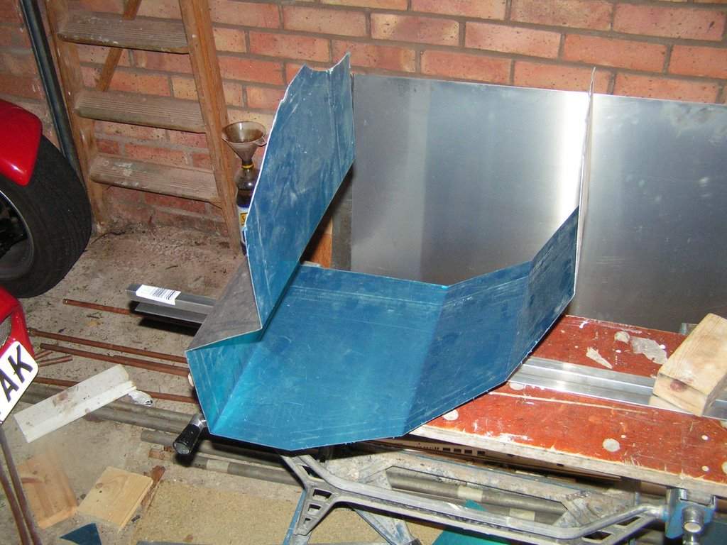
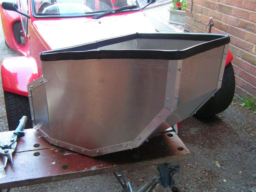
Boot box design and install - May 2008 When I originally built the Mojo, I tried to position items in the engine bay such that there was a reasonable amount of free space to the left of the engine, above the gearbox. The intention was to leave the option of fitting a small storage compartment in the long run, but this is a job that I have never got round to - until now! Although in real terms the amount of storage space will be small, it will be useful to have a secure storage compartment in which to leave things when I leave the car unattended, and somewhere to stash items on the occasions that I have a passenger in the car. The compartment is admittedly likely to get rather warm, but so long as I avoid putting my sandwiches in there I think it will be fine! I intend to use some heat reflective mat on the outside of the box to help matters. Ideally I wanted the box to be easily removable so that I can take it out for engine access, shows or trackdays, and so I decided the only way to come up with a design was to make some cardboard templates. After a couple of trial runs I came up with a design that made reasonable use of the available space without being too overcomplicated, and which could be lifted out without the need to start removing engine bay components. It is not a simple 'box' at all! The lowest part of the box sits directly onto the top of the upper rear chassis rail, and extends rearwards as far as the fibreglass tub. The flat base then kicks up to clear the clutch cable. The left hand side is a flat vertical sheet, but the right hand side is angled to maximise space whilst also clearing the coil pack and pressure regulator- see the pics lower down if that doesn't make sense! The obvious material to use for the box was aluminium sheet as I had plenty left over from the original build. I decided that I could form the rear, base and front of the box from a single sheet, forming the corners in the workbench as I had on occasions when doing the original chassis panelling. The sides would then be joined on using extruded aluminium angle section - these will be rivetted to the sheet. Having finalised the design I took dimension from the cardboard template and marked and cut out the largest piece, and then made the series of folds - all 6 of them! The end result is pictured below:
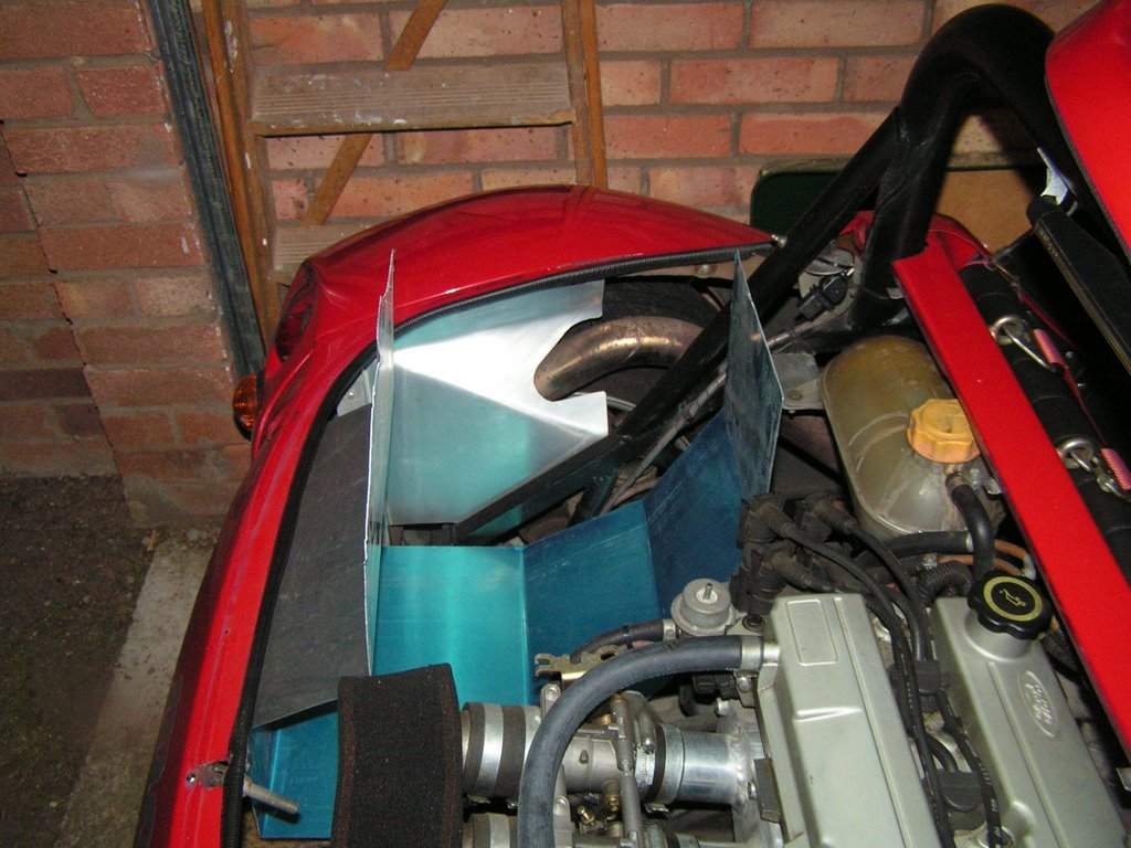
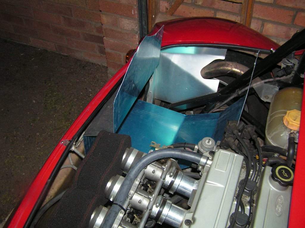
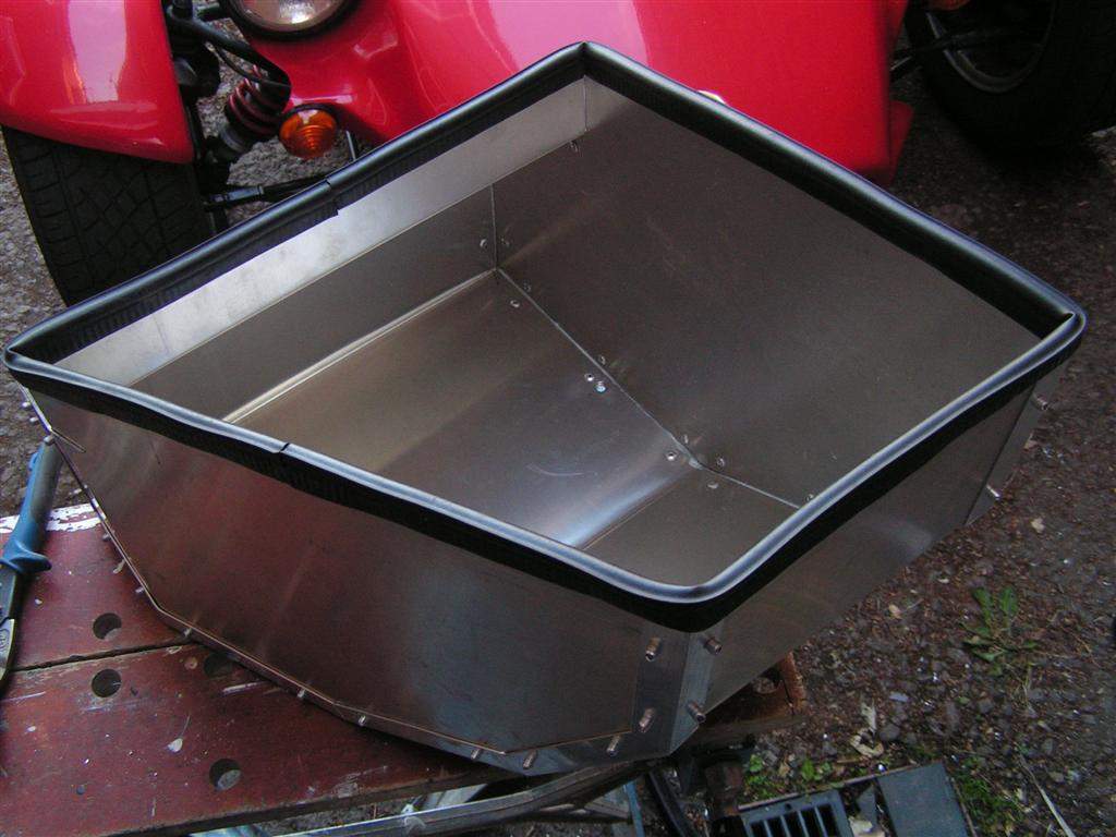
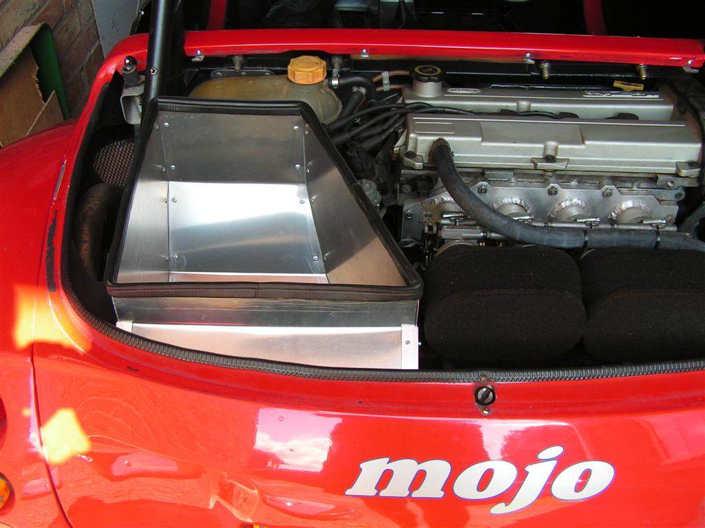
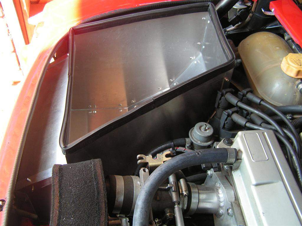
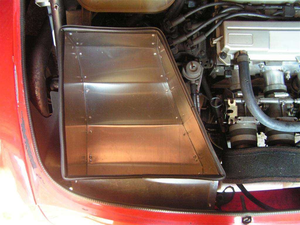
The moment of truth was then checking that it fitted into the engine bay, which it did, just! These pictures hopefully now explain how this is all going to work!
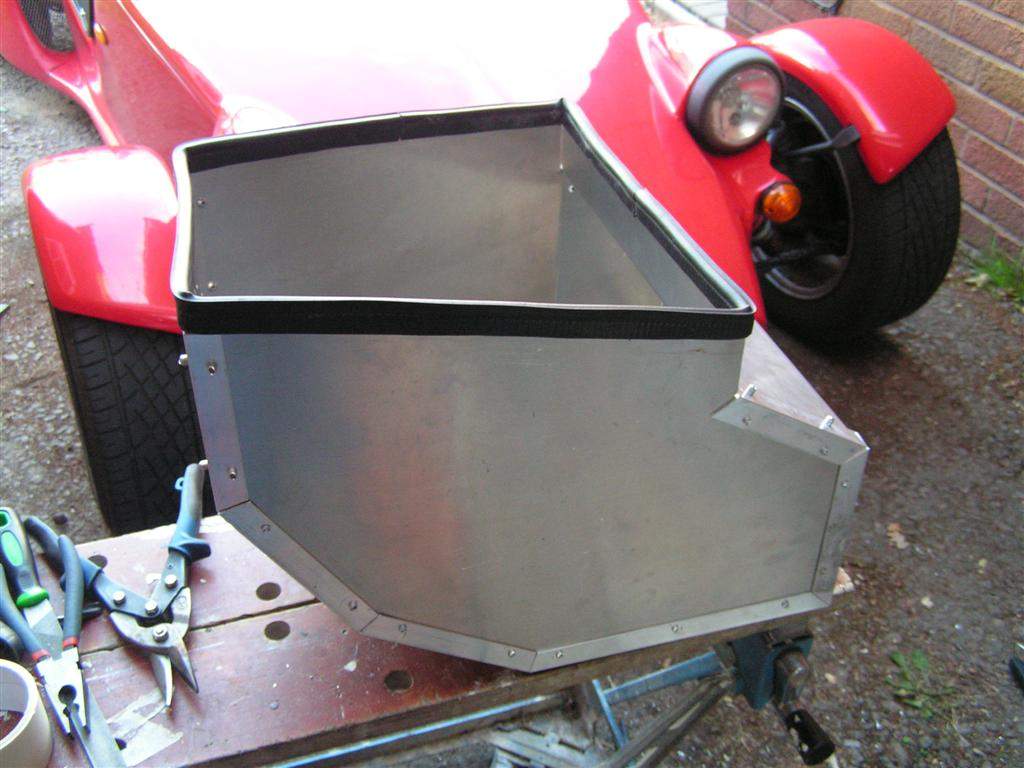
The next job was to mark ouf the 2 side panels, which was now easier as I had the first part of the bootbox to work from. The right hand side panel also has a fold to maximise the use of the available space. These 2 panels and the original panel were all left oversize at the top edge to allow me to trim back to fit against the engine cover once trial fitted in place. I then cut various lengths of aluminium angle section with mitred joints, and joined everything together, riveting the angle to the side panels but at this stage using nuts and bolts to attach the angle to the base panel - this would allow me to take the box apart when cutting the top edge down to fit. I then trail fitted the bootbox and marked the top edge as best as possible. I then took the bootbox apart, trimmed the top edge, and then put it back together for another trial fit! After a couple of iterations I had a good fit to the underside of the engine cover with the rubber seal in place. The bootbox was secured in place by fitting 2 rivnuts to the top of the rear upper chassis rail, so that the bootbox could be secured by fitting 2 M5 caphead bolts. Ideally the box could do with another mounting point to firm up the mount, but I am still thinking that one through at the moment!
|
|||||||||||||||||||||||||||||||||||||||||||||
|
|
|||||||||||||||||||||||||||||||||||||||||||||||