 |
|||||||||||||||||||||||||||||||||||||||||||||||||||||||||||||||||||||||||||||
|
|
|
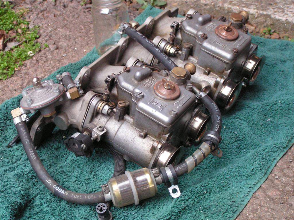
Throttle body conversion diary 2005 10th November: Won an
auction for some GSXR750 TBs in Canada, the winning bid was for just
over £70. They are of 2000 vintage so should have the 270cc/m
injectors, and also the plastic & aluminium fuel rail that can
be modified. Postage is about £15, so given that these are now
regularly selling for £120+ in the UK, I should save some
money.
4th December: Extended the throttle linkages. I did this by making up 3 aluminium plates from some angle aluminium I had lying around (B&Q normally have decent supplies of this). I trimmed off almost all of one leg of the angle section, just leaving a 2mm return to give the plate some extra bending stiffness. I then rivetted these to the original linkage plates using the smallest rivets that I had in stock. A quick re-assembly proved that the linkages worked perfectly.
5th December: Blocked off the holes from the secondary butterfly spindle with bolts and chemical metal, then left overnight to cure (in the warmth of the house...). 6th December: Assembled the TBs onto the 5mm threaded rod I bought from B&Q. Conveniently, the nuts just sit into the recessed faces on one side of each TB, which locates each TB more securely. I trial fitted the bodies to the manifold and then measured from the front face of the TBs to the cylinder head flange to compare to the existing carbs. I then trimmed down the silicon hose so that the TBs protrude a similar amount from the cylinder head. I think they are starting to look quite good!
18th December: Picked up a new Bosch fuel pump from a local ebay seller. It is a Bosch part, PN 0 580 464 070, which has barbed inlet and outlet connections to take push on hose & clips (I am avoiding threaded connections to cut down on expense).
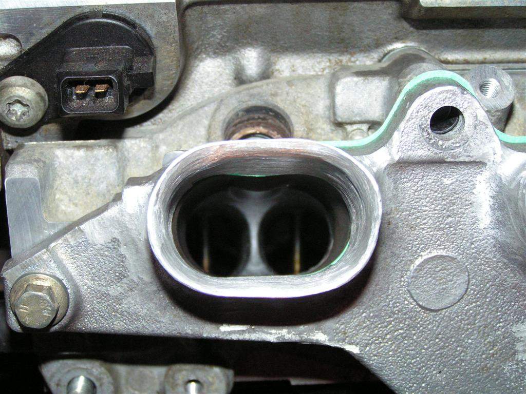
22nd December: Finished opening up the ports on the original Ford manifold. This took a good couple of hours, but I'm pleased with the end result. The wall thickness of the runners is now 2-3mm rather than 5mm, so the step from the silicon hose is much reduced.
2006 13th -15th January: Bought another reel of 8mm copper microbore central heating pipe for my new fuel line for the bargain price of £8 for 10 metres from Building and Plumbing Supplies (the remainder of my original reel had been passed on to Andy Sayle, another Mojo builder). This spurred me on to do some work on the car this weekend. Firstly, I removed the nose and then disconnected the fuel lines from the fuel tank and removed the tank, in order to create some temporary space to help with deciding where to mount the new high pressure fuel pump. The pump is supposed to be gravity fed, but given that the fuel tank sits directly on the flat floor, having the pump below the tank is not possible. So, I wanted to fix the pump to the top of the floor to mount it as low as possible, and I found a gap just in front of the driver's footwell, near the heater matrix. I then made up a bracket out of aluminium to fix the pump to the floor incorporating a bracket for the feed fuel line. I will use rivnuts fitted to the bracket, but I don't have any in stock so that will have to wait.
I then removed all of the tunnel panels in order to fit the second fuel line. This was fed through from the front, until it sat roughly in place, and then the routing was neatened and the line P-clipped in place. To save drilling yet more holes, I have placed one clip around the original fuel line, a corresponding one around the new line, and then rivetted the P- clips together. The original line is well supported, so I don't see a problem with this. For the time being I taped over the ends of the line to stop any debris getting inside. 20th January: Phoned Emerald to find out about upgrading my ECU to injection. They confirmed I could do the upgrade myself, so after handing over my £150+VAT, I received the update file in an email, potentially the most expensive email I have ever been sent! Phoned Think Automotive to order a fuel tank breather and an 8mm-12mm hose reducer to cope with the 12mm input on my fuel pump. 21st January: Parcel arrived from Think, the valve is much smaller than I expected, very neat. I will fit it to the fuel tank cap, so that I can easily tighten the locknut. 28th - 29th January: The trumpets arrived from ITG, and very nice they are too. They have a 48mm internal diameter, the TBs are approx 48.5mm at the inlet so there is a small lip, but I don't think this is too significant (the TBs taper down to 42mm anyway). Unless I think of a better method, I will attach them with some suitably sized hose and clips, although I'm aware that there will be 16 hose clips on the full setup, which weigh a surprising amount. Given that the trumpets only have an air filter to support, they don't need to be attached as firmly as the TBs to the manifold, but I currently can't think of a lighter, neater solution... I will re-use my existing air filters, as they need to be compact to fit under the bonnet.
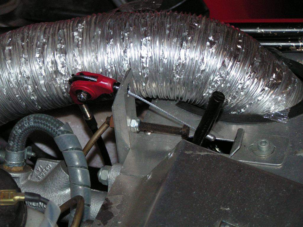
My attention then turned to the throttle linkage. I am going to mount the TBs with the injectors below, which means that the throttle cable will attach at the left hand end. Unfortunately, this also means that the original cable stop on the TBs for the cable outer now sits above the TBs, so the outer cable would have to run over the engine cover... I am clearly going to have to fabricate a new bracket to secure the cable outer below the TBs. However, the cable will have to enter this cable stop pretty much a vertically, and I probably don't have enough cable to reach. Hmmm. Re-routing the existing cable down the tunnel (currently it runs down the side of the chassis, underneath the bodywork, and round under the right hand carb onto the bottom mount linkage on the Weber carbs) is not going to be possible as it won't come out without removing either the body or the rivetted-on internal trim panel, neither of which I wish to do. I could run a new cable down the tunnel, but I had another idea: I could use a bit of a mountain bike inspired trick for getting cables to run around tight corners, and use one of these roller devices. I then hope that by removing a bit of slack on the routing of the existing throttle cable outer, I might be able to re-use the cable to reach the left hand end of the TBs- the roller device will essentially allow the cable to run under the TBs horizontally. Whatever I decide, I need a new bracket to support the cable outer/roller, so I set to and made one up out of thick aluminium plate. This is a bit of a complicated shape to clear various parts of the TBs.
Fitted the fuel tank breather by drilling a suitable hole in the fuel tank cap. It doesn't interfere at all with the removal & tightening of the cap, which is great.
1st February: Reluctant to spend 15 quid on the aforementioned mountain bike brake roller device, I spotted that the Rollamajig is a lot cheaper, but turns the cable through an angle greater than 90 degrees. This is designed to work with bike gear cable which is a bit thinner than brake cable, but should still be strong enough. I may even be able to use the existing throttle cable inner, but it may be too thick. However, to mount under the TBs I need at most a 90deg change in direction, so I had a re-think. Then I had a brainwave- at the front of the car the throttle cable runs through a 180 degree loop, see the picture for reference:
I could use the rollamajig here to turn the cable through 110 degrees or so, eliminating a big loop of cable, which would then give me an extra 300mm or so of cable to pull through towards the rear of the car, enabling me to connect straight onto the throttle body linkage. So, I ordered the device for £6.99. 4th February: The rollamajig arrived, so I pulled out the existing throttle cable inner to see if it would work. It won't! So a new inner cable is required, approx 3.35m long. My plan was to use a gear cable off a tandem, but these are mostly 3.05m long. The one supplier of a 3.5m cable I did track down wanted to charge me £3.99 for the cable and £5 for postage! I'm a Yorkshireman, so don't like being ripped off, so I continued my search elsewhere... 6th February: Trimmed down the aluminium bracket that will support the throttle cable to make it look neater. I also had to put an extra fold on the bracket to make sure it cleared the samco hose completely. 10th February: I've had suggestions to try getting the cable by the metre off a reel from B&Q or similar, and then just use an extra solderless nipple, or to try a motorbike repair place to see if they can make one up for me. 14th February: Package arrived from Vehicle Wiring Products containing some essential supplies, such as P-clips, connectors for the injectors and some other wiring stuff. Managed to get hold of a pipe flaring tool from a colleague at work, so I can now flare the ends of the copper fuel line to prevent the rubber hoses from blowing off under pressure. I popped into JM Motorcycles in Leamington, and spoke to a very helpful chap who pointed me in the direction of JJ Cables in Lighthorne, who apparently manufacture cables and will make up practically anything. Typically, this is about a mile from where I work, having trawled the web, the yellow pages, all local bike shops etc etc. Hopefully the search is over, I will pop in during my lunch break tomorrow... I've got alternative transport to work this week, so I'm hoping to get a chunk of work done. First job was to take off the nose again, remove the fuel tank, and make a start on mounting the new fuel pump. I finished off the pump mounting bracket, including setting 4 M6 rivnuts. I then fixed a metre of hose to the inlet and outlet, as I will not be able to attach these once the pump is in position. I added some p-clips to support the hose, and then made up 2 new lengths of wire to power the pump, with ring connectors to connect to the threaded terminals on the pump. The cable was spiral wrapped and secured to the pump mounting bracket with cable ties. This whole assembly will then be able to be fed into place once I've drilled 4 holes through the floor (hopefully in the right place...) and bolted into position. However, I think I might have to remove the heater matrix to get the pump into position, which is a bit of a bind, but there is nowhere else to mount it, so it's what I'll have to do! 15th February: Popped into JJ Cables in Lighthorne, they are making a cable up for me to collect tomorrow! Great, that's one more problem solved... Tackled the job of fitting the new fuel pump. I still wasn't sure if I could manage it with the heater matrix in place, but to create some working space I removed the heater blower, battery and steering column link. I then found I could manoeuvre the heater matrix and its housing sufficiently, so draining the coolant wasn't necessary. I made up a template of the four rivnut mounts to transfer to the floor panel, which was drilled through from below after triple checking that it was in the correct place... The fuel pump, bracket and the associated fuel lines and wiring were then fed into their new home, and thankfully the 4 bolts fitted straight into the rivnuts from below. I then re-assembled the heater assembly, bolted the steering column link back in place, and then worked out that this apparently simple evening of work had taken me about 4 hours to complete...
16th February: Collected the new throttle cable from JJ Cables, I've had it made up with an identical nipple to the original cable. They charged me £5 which I thought was very reasonable. Had a few practice runs using the flaring tool on a spare bit of 8mm pipe, and then created one flare on the new feed pipe already fitted to the car. I had to do a bit of careful filing as the resulting flare had some sharp edges- I had been warned that this could cut into the rubber hose. I then wrapped the rubber fuel lines attached to the pump in heat reflective mat where they pass near to the radiator tubes as a precautionary measure, and bent the copper fuel line with flare into a suitable position to attach the 8mm hose from the pump. An extra P-clip was then fitted to support the copper fuel line 17th February: Attached a new low pressure fuel filter to the feed to the fuel pump, to prevent any grit getting into the pump. 18th February: The postman arrived with a parcel containing my fuel rail. I had sent this off to Michael, a helpful chap who has converted his Westfield using GSXR750 TBs. He has the facilities to make some longer link pieces to suit the new TB spacing, and at the same time making up 2 end pieces to convert the rail to a through flow with feed and return. Here is the result:
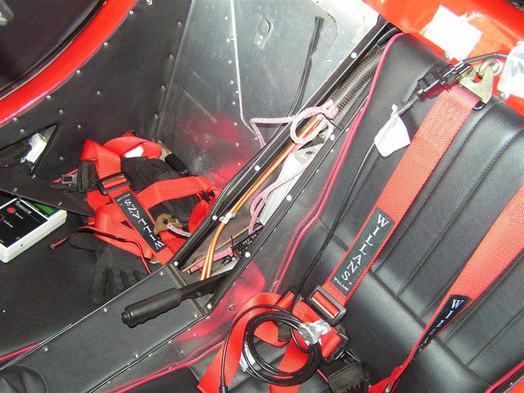
Checked that the new throttle cable fed through the rollamajig successfully, and then pondered the throttle setup. I was aware that the bike TBs required less 'pull' of cable than the carbs, so I checked. The TBs require approx 25mm of cable from closed to fully open; the current carbs are nearer to 40mm. To prevent the throttle pedal becoming too sensitive, I decided to change the cable stop position on the pedal. I determined the new position by simply using the current pedal travel as a guide, and then measuring the position which would pull approx 25mm of cable. I then removed the pedal and drilled a new hole large enough for the inner cable, and then opened this out to a depth of a few mm on one side to give the nipple a small housing:
I decided that the cable should ideally attach to the pedal at a downwards angle to give a fairly linear pull, so then worked out a way to modify the current cable stop bracket to accommodate the rollamajig, whilst still allowing the old cable routing to work in the short term (to allow me to use the car on carbs for the next week or 2!). I removed the cable stop bracket and cut away some material to allow me to bend the aluminium profile. A picture speaks a thousand words, so here are the before and after photos:
I then made up a small adapter to allow the old system to work in the short term:
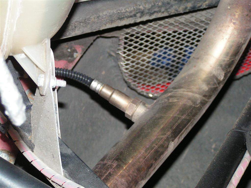
19th February: Put the car back together in preparation for the journey to work tomorrow morning! 24th February: Won an ebay auction for a tested working Vauxhall Astra GTE fuel pressure regulator, this has barbed ends so can just be plumbed in to the return fuel line. Once again, a bargain at £2... This is only a 2.5bar regulator, which by my calcs (based on some internet research) should be enough for about 170bhp if the injectors are the 270cc/min that I think they are. So, this should be OK (I'm not expecting more than 160bhp) if the injectors flow what I think they ought to... If not, I'll be after another regulator, rated at 3bar+. 26th February: Made a start on removing the exhaust link pipe in order to get the wideband boss welded in. I sourced the boss from Bill Shurvinton, who will also supply me with the wideband kit in a few weeks time. Unfortunately, removing the exhaust was not as easy as I had hoped- the two stainless clamps do not evidently use stainless bolts, as these had rusted solid. The first one sheared when I tried to undo it, the second refused to budge so was forcibly removed with the help of a cutting disc in the dremel. I will need to get 2 new clamps in order to re-fit... Once the clamps were off, the exhaust could be removed easily enough.
I made a start on the extra wiring. First job was to cut off the 3 pin connector on the fly leads off the throttle pot . This I replaced with a new 3 pin connector from vehicle wiring products, to which I have both the male and female parts! I then modified the connectors on the 4 injectors. Superficially these look like standard mini timer male plugs, but they have some extra ridges moulded in. In true kit car style, I carefully dremeled off these ridges to make the standard mini timer plugs fit. I then took some rough measurements for the length required for the injector wiring to reach the ECU & power feed in the tunnel. 27th February: Took my exhaust link pipe into work today to get the wideband boss welded in. Dave (the welder) opened the hole up to allow the boss to sit in, and then did this artful bit of welding:
Ordered some new exhaust clamps, so the car should be driveable again by Wednesday. Continued with the wiring for the injectors and new throttle pot in the warmth of the house, based on the measurements I took yesterday! 1st March: Had a visit from Murray, who is building a Luego with Zetec on bike TBs. He had kindly offered (via the locostbuilders forum) to sell off some of his 51mm ID fuel hose for mounting the trumpets to the TBs- he had bought a metre of the stuff from Burton Power and I only needed 200mm! The hose is pretty hefty stuff, the walls are about 6mm thick which means my current jubilee clips aren't quite big enough- something else to buy! 8th March: Made up a bracket for the high pressure fuel filter. I will mount it just below the TBs off one of the manifold bolts. 31st March: Made up a bracket for the fuel pressure regulator. I debated for a while where best to mount this, in the end I am using 2 existing holes in the coil pack support bracket to mount the FPR. This should give fairly neat runs for the flexible fuel hose. 1st April: Made up a couple of brackets out of U-section aluminium strip to take the weight of the throttle bodies off the silicon hose. I'm not sure if this is absolutely necessary, but decided it was better to be safe than sorry. As per usual, these brackets were quite difficult to make, but I'm pleased with the result. Each one will mount to one of the manifold retaining bolts.
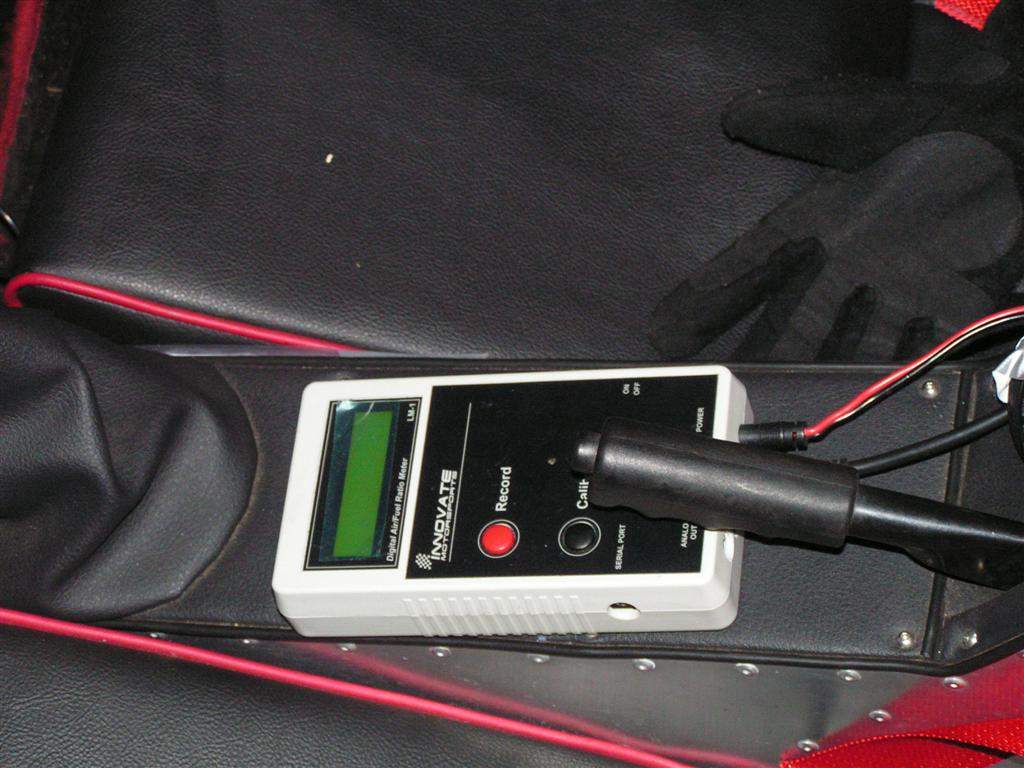
3rd April: The wideband kit arrived today, so I spent a while trawling through the manual. I will try to get it installed before the weekend, to reduce the seemingly endless list of jobs I have to do to complete the conversion! 4th April: I decided to start fitting the Innovate Motorsports LM-1 wideband sensor that I have on loan. Basically this kit can be used on its own to give a display of air fuel ratio (AFR) as you drive along, and consists of:
I decided to initially wire the sensor up in its simplest setup, so I screwed the sensor into the exhaust, made up some cables to temporarily connect the LM-1 to a 12V supply and then tested it out by turning the engine on and then swithcing on the LM-1. Hey presto, the engine is idling at an AFR of about 12 (quite rich), and all seems to be working fine.
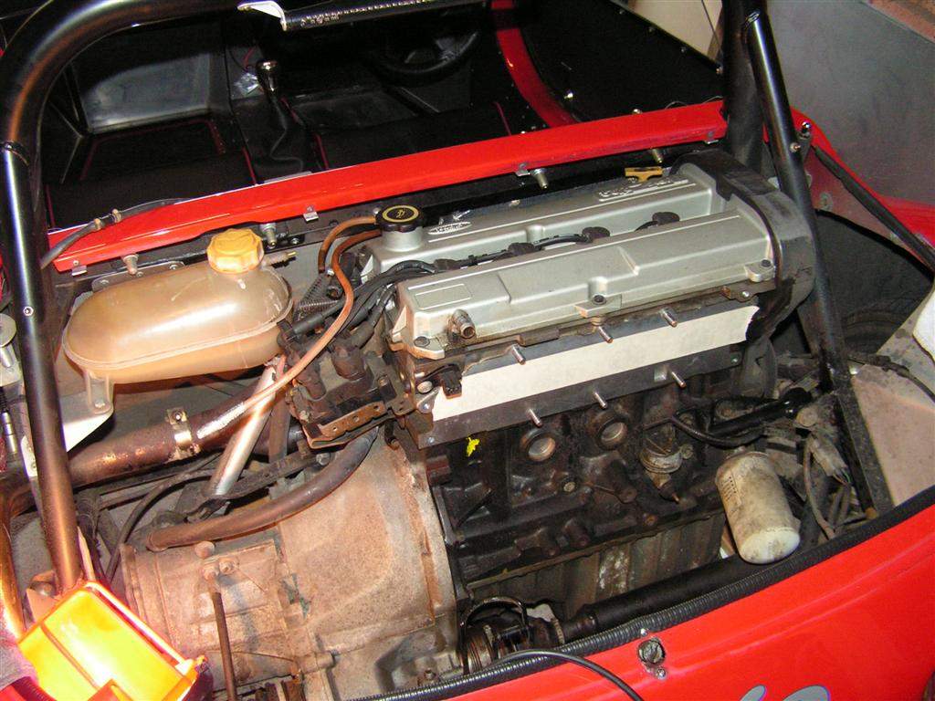
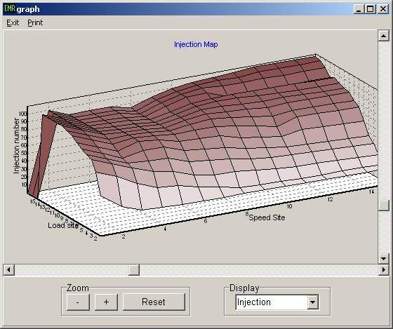
While on the subject, I'll just write a bit about my intentions for mapping the TB setup using the wideband. Last year I stumbled upon a utility written by a chap called Chris Good from the se7ens mailing list. In simple terms, emerald-afr can analyse data from driving on the road, and use some statistical analysis to make suggestions for tuning the injection mapping. Chris used the software on his own car, and then for comparison purposes took the car to Emerald's rolling road. The map he had created was pretty much spot on! So, how does it work? Well, firstly, it relies on the Emerald ECU's data logging capability (it does also work with some other ECUs). The analogue output from the wideband is connected up to one of the Aux Inputs on the Emerald. The Emerald is then configured to log key parameters, principally load (via the throttle pot), engine speed, and AFR. The car is then taken for a drive, recording this data, which can then be saved to a file. Emerald-afr can then process this file, and display an AFR for each load & speed site on the map for which it has gathered data. The clever bit is that the number of samples logged at each site is used to give an indication of confidence in the data, plus an indication of how much to richen/lean off the fuel mixture at each site is given, based on running at a stoichiometric ratio (14.7AFR) at light throttle down to about 12.5AFR at full throttle (although this target AFR vs load can be changed if necessary). If a structured approach to your driving is taken, a reasonable map should result after 4 or 5 iterations. The general technique seems to be to find a quiet road, select 4th or 5th gear at about 1250rpm, and then apply a fixed amount of throttle, holding the throttle position as engine speed rises to say 3500rpm. Then slow down and repeat at a slightly larger throttle position. Ideally, a slow acceleration is better as it will mean more samples at a given engine speed site, so for larger throttle angles a bit of left foot braking should help to load the engine without too much acceleration. After doing this for the first half of throttle travel, pull over and process the log file, and tweak the map. Keep an eye on those sites further up the map than you have data for, and if they start looking stupidly high or low, then adjust them roughly into line. Then repeat the driving process, but allow the revs to increase to say 4500rpm (you will have to start using 2nd & 3rd gear and lots more left foot braking to stay legal!), then pull over, process and tweak the map. This will allow some more fine tuning of the lower end, and gradually bring the higher engine speed sites into the ballpark. The key is to not go straight for full throttle & max revs, as if the base map is seriously out, you risk damaging your precious engine. If this all sounds a bit daunting, I am reliably informed that it is really a very straightforward process! I will let you know once I have done it! The beauty of this method is that once you have a map pretty much in the ballpark, there is still nothing stopping you from continuing to log all of your journeys in the car, to continuously improve the map. Emerald are reputed to be working on some code that will actually do the map tweaking for you, so that it will essentially self learn the injection map based on the AFR input. However, as they are such busy chaps, upgrades like that tend to take quite a while, so in the meantime Emerald-afr is definitely the way forward! 5th April: Drove the car to work with the wideband turned on (once the sensor is in the exhaust, it should always be powered when the engine is running to prevent damage). This was quite enlightening! At idle the engine runs at about 12AFR, which is quite rich. At light throttle it then goes to 14-15AFR, which is about spot on, while full throttle sees about 11AFR, again a bit richer than you would aim for on injection. So basically the carbs are in the right ballpark, but do allow the AFR to vary quite a lot more than you would aim for on injection. In the evening, I decided to test my injectors for operation after a series of threads on locostbuilders concerning sticking injectors! My injectors can just be connected directly to a 12V supply to test. Injectors 1 & 2 created a nice gentle tapping noise, but no.3 stayed ominously quiet... I tried a couple of gentle taps on the body of the injector and tried again. Still nothing. 2 slightly less gentle taps, and I tried again, and this time there was a tap, but quieter than injectors 1 & 2. However, repeatedly connecting the injector to the 12V supply started to ease it off, until it sounded pretty much the same as the others- phew! Injector 4 proved to be like 1 & 2. I had bought some injector cleaner petrol treatment to add to the tank after the conversion, so I decided to soak the injectors in some neat injector cleaner overnight to help clear off any remaining gunge. Let's hope that sorts them! 7th April: Drove the car to work as usual this moming, but once I arrived home it was time to crack on with the conversion- the aim is to drive to work on Monday on the throttle bodies! Needless to say there were various comments made at the local Sylva Meet yesterday expressing doubt in my seemingly ambitious plans. We will see...! I started at about 3pm, and began by disconnecting the fuel lines to the carbs. I then removed the nuts on the inlet manifold studs, and removed the carbs, manifold and linkage as one assembly. This will make it easier to re-install the carbs should it be necessary...
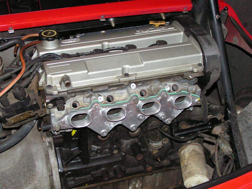
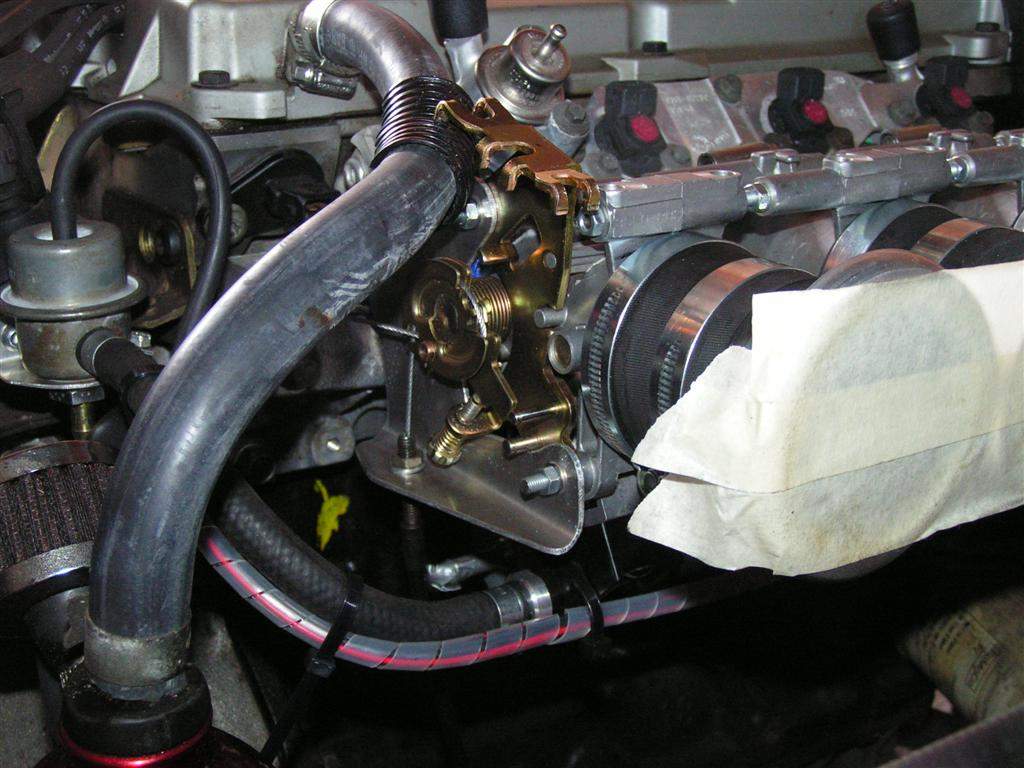
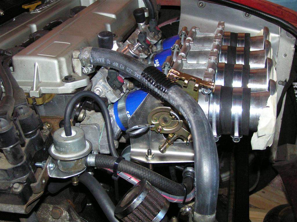
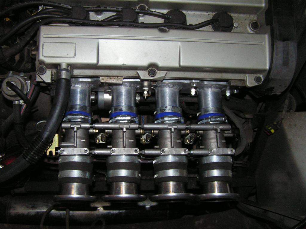
I then had to remove the inlet manifold studs, as the chopped down zetec manifold uses 70mm long bolts to secure. The sealing face of the head was cleaned up, and then the two parts of the zetec manifold offered into place using new gaskets.
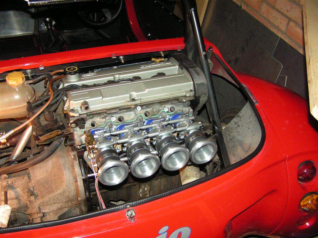
I then offered up the throttle body assembly and tightened all hoses and the manifold bolts. Finally I bolted the original fuel rail in place, simply to bung up the holes in the original manifold for the time being.
I needed to relocate the catch tank as the pipe from the cam cover was in the way of the new throttle linkage. Thankfully, I originally made this as a clamp-on bracket to take a bike bottle holder- it was a simple matter to move it a few inches further to the left, and add some slightly longer pipework. Next job was to generate some slack in the throttle cable outer in the engine bay, to enable it to reach to the left hand side of the TBs. I fitted the rollamajig at the front of the car, and then pulled the excess outer cable through to the rear- I gained about 400mm of cable length at the rear of the car by doing this. The cable could then easily reach the throttle bracket I had previously made up- it is now routed along the lower chassis rail and passes around the back of the sump, and then up to the throttle bodies from below.
That was about as far as I got, I called it a day at about 11pm! 8th April: Today was a day when progress seemed slow- fuel lines and wiring, and all the associated stuff, takes a long time. Firstly I sorted the fuel lines. I bolted the fuel filter and pressure regulator in place in the engine bay and routed hoses to suit. Then I connected up the new fuel pump at the front, and switched over the original fuel feed to act as the new fuel return.
The final big job was the wiring- I needed to connect the new throttle pot and the injectors to the ECU, which meant removing the ECU from its snug home in the rear of the tunnel. This proved to be an entertaining process, but eventually the ECU succumbed and allowed me to remove it! I then had the interesting task of disconnecting the existing throttle potentiometer from the ECU multiplug, in the confines of the tunnel. Scraped knuckles were the order of the day, but once again, eventually the new pot and injectors were wired in.
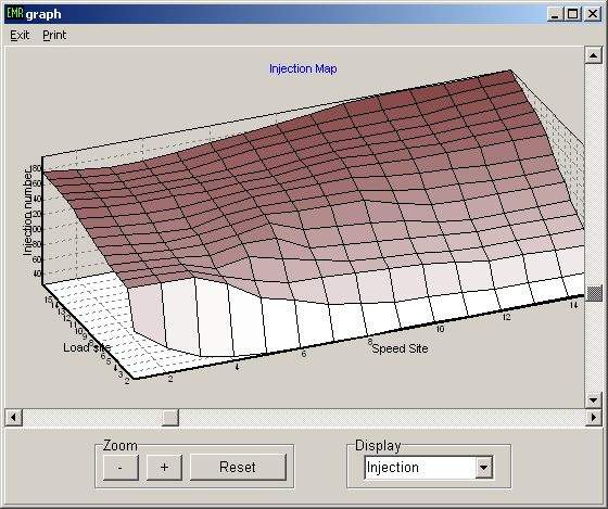
So, it was now crunch time, at about 5pm on Saturday. I connected the laptop to the ECU and uploaded my chosen base map, and then calibrated the new throttle pot. The fuel pump fired into life once the ECU was fired up, as it primed the fuel system before shutting off. A quick check round found no fuel leaks, so a good start. It was time to try and start the engine. Nervously, I turned it over. The first couple of goes showed no sign of any fuel being ignited at all- I guess the injectors were probably just pumping air as the fuel system was purged. On the third attempt, distinct signs of life, and on the fourth, it started! Wahey! To start with, the engine needed a lot of nursing with the throttle, and was running pretty roughly. I had tried to align the butterflies visually (all 4 can be adjusted independently), with the intention of checking the balance with my carbalancer once running- however you need a relatively stable idle to do this, and stable was not the word that sprang to mind! The engine would try and die one moment, and then race up to 5000rpm the next, seemingly unrelated to the throttle position. A bit of trial and error with the balance adjusters and scaling of the fuel map, and I finally managed to get it to idle well enough to set the balance properly, at which point things started to come together. I called it a day at about 7pm... 9th April: So, I now had a running engine, but I was still nervous about hopping in and driving the thing. Applying a small amount of throttle at idle resulted in the engine stalling, but larger throttle openings seemed OK. I decided to have a tentative drive around the block... All went well, that massive flat spot was still there though, meaning you had to apply more throttle than you would normally need to stop the thing from bogging down when pulling away from rest. This was a bit worrying, but I hoped to iron it out with the mapping... So, I chose a local, straight, quiet road, and drove up and down between 2 roundabouts about 4 times, then pulled over and processed the log file. Sure enough, there was a massive lean spot when the throttle was cracked open, and increasing the fuelling helped with the problem. However, I noticed something else that wasn't right, and realised a mistake I had made. Cruising at light throttle was often carried out at load site 0 in the emerald map, normally a load optimised more for overrun fuelling and idle. I remembered that since balancing the throttles, I had not recalibrated the throttle pot. Having done this, things improved markedly again, with very slight throttle application now moving to load site 1 on the map. With the flat spot becoming a distant memory, I now concentrated on the mapping approach I detailed a few days ago, concentrating for the time being on up to about 3500rpm across the first half of throttle travel. After an hour and a half and 3 iterations, things were looking promising,with the AFR in the 13-15 region, so I called it an early day at about 6pm! There is still a lot of mapping to do to get things spot on, but the car is now drivable for the journey to work tomorrow. Yippee. All my doubters have been proven wrong! 10th April: Drove the car to work without a hitch, gathering more data as I went. At lunctime I came up with an excel spreadsheet that automatically enters the recommendations of the emerald-afr results.txt file into the emerald map file- this should speed things along nicely! It is still not completely robust, but I can make it available if someone would like to take a peek- just drop me an email. I decided to come home the scenic route, searching out some straight stretches of road where I can see when I have plenty of clear road ahead and behind. With the map improving for lower loads and revs, I decided it was time to up the game a little, and I moved on to higher loads and revs. The map seemed to be in the right ballpark, so after another iteration or 2 I did some runs at high revs, for different loads, from overrun to full throttle, using left foot braking to stop the car from accelerating. These were mechanically unsympathetic times! The brakes took on the feel that they have had after trackdays in the past, just to remind me that they were working hard- hopefully they will recover with a few more gentle miles, as they have done before. Happy that the mapping was going reasonably well (the map is still a long way off perfect though), I enjoyed the last few miles of open road and just had a blat! The engine picks up so much better from below 2500rpm compared with on carbs, but it has also improved noticeably at the top end too- above 4000rpm and it flies, and sounds a bit different at these higher revs too. I guess the 32mm chokes I ran before were perhaps partially to blame...? I will continue collecting data every time I drive the car, including my planned trip to Curborough sprint track on 20th April, until I am happy that the map is optimised... 27th April: Well, I have been now driving the car for nearly 3 weeks on TBs, and the map is now coming together pretty well. I only have one problem area, and that is when you crack open the throttle from closed. I think the problem is principally due to the fact that the load sites in the Emerald map actually give quite a coarse resolution at small throttle openings, and I think this is made worse by the fact that if anything my throttle bodies are slightly oversized for the engine. This means that a very small change in throttle angle leads to a big change in air flow. The result is that I can get the map to give the right air-fuel ratio at bang on load site 0, and at bang on load site 1, but the linear interpolation between these points is not sufficient to capture the air flow characteristics. This means that as I crack open the throttle, the mixture initially goes lean, then comes back to target as I reach load site 1. Ideally I need an extra point or 2 in between load 0 and load 1, to increase the fuelling above what the linear interpolation currently calculates. I had read about a trick to gain resolution at lower throttle angles on the se7ens mailing list, using a resistor between the 12V and sensor wires on the throttle pot. I decided this had to be worth a go, even though it would mean the map would need re-jigging. I tried a 2.2kOhm resistor, which gave about double the resolution at low throttle angles (at the expense of slightly worse resolution at full load). However, it turns out that the 5kOhm throttle pot on the TBs does not use the full range of travel, so the additional resistor also gave the effect of reducing the voltage range over which the throttle pot gave out a signal, and this resulted in an increase in noise which could be clearly seen in the logfiles recorded whilst driving. Hmmm. The end result was that the car didn't really feel any better, so I removed the resisitor. What I could really do with is a user-definable load position in the Emerald map- frustratingly, something which you can do if you run MegaSquirt, but not on the Emerald. I decided to concentrate on getting the bulk of the map perfected, whilst pondering other ways to improve this low throttle drivability issue. Mapping the upper parts of the rev range at high loads was entertaining to say the least! Smooth, straight, quiet roads were the order of the day. I found that holding the car at a steady speed using left foot braking was OK for lower revs & loads, but it started getting hairy at high revs & full throttle, plus the brakes got rather warm! I therefore just resorted to repeated runs up to the red line in second gear- unfortunately, this means you only gather a data point or 2 for each load & speed site for each acceleration run, so lots of time (& fuel!) was consumed. However, the map is now looking quite sorted, with the exception of the nasty step at the bottom left hand corner- this is where I need the extra resolution:
I've got a few other maps from zetecs on TBs and they are much smoother in this area- take this one for example:
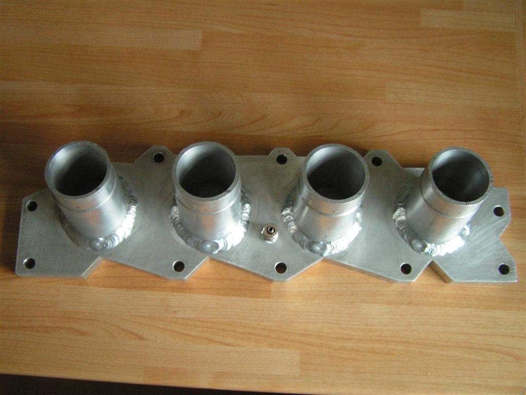
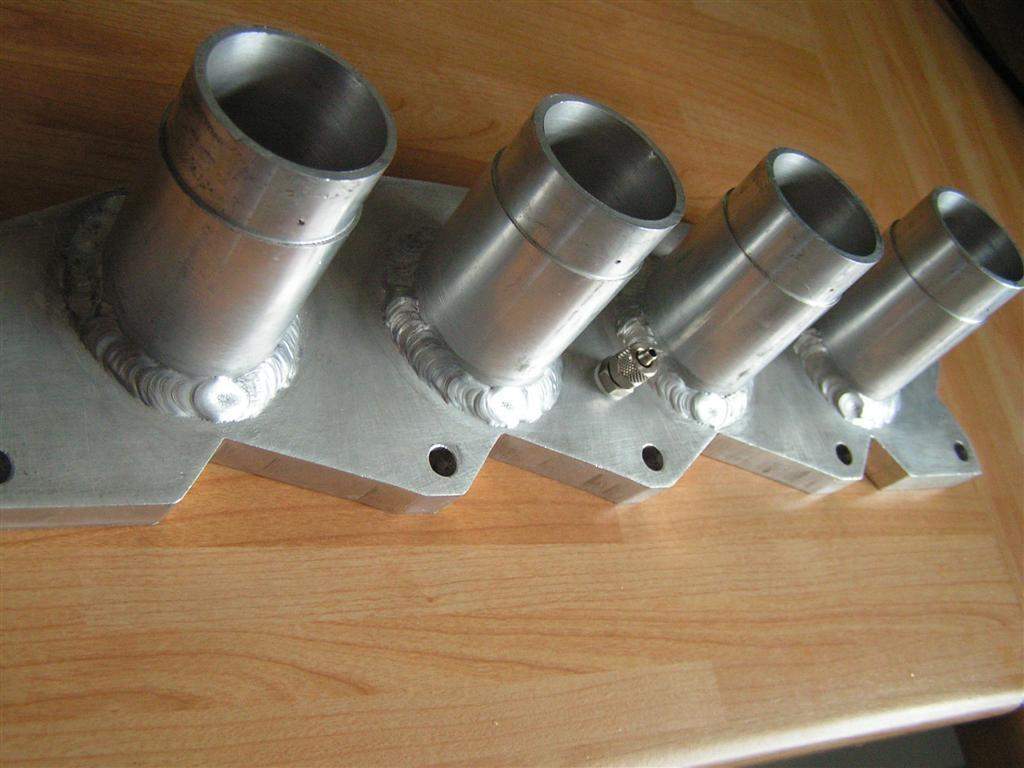
Thankfully the car is still very drivable with this low load glitch, so I am not too worried- I had just hoped for better. My next plan is to try slightly increasing the load 0 sites from 1500rpm upwards, compromising completely closed throttle running, but hopefully improving the running whilst operating between load sites 0 and 1. I can then activate the overrun fuel cutoff to stop the car eating fuel on the overrun, although this will need deactivating below about 2000rpm, so the 1500rpm load site will be a compromise. I will try and have a chat with Dave Walker at Stoneleigh this weekend, he is due to be on hand at the TotalKitCar stand... Another interesting thing I've noticed from occasional glances at the Emerald logfiles is that the injector duty cycle is peaking at about 83%, which is just about perfect- generally 85-90% is the guideline. Go over this and the injectors are nearing maximum capacity, below this and your injectors are oversized for the application, which can give problems with idle running. So in my case the GSXR injectors are just about right (running at 2.5bar), and would probably therefore fuel a fairly standard 2.0 zetec (at 3bar or so). I've also now uploaded a spreadsheet detailing the costs of the conversion. I have now sold most of the redundant bits relating to the carbs, so the total net cost has come in at approximately £270, which is pretty good value for money! 4th August: A final update on the throttle bodies! More fiddling with the map eventually dialed out that flat spot on light throttle application, so that is now completely fixed. I didn't use the wideband at all for this final tuning, just changed to map subtly until I got the results I wanted. I contacted Emerald about a software update to enable me to add an extra load site, but they asked me to wait for the official release of the new software (which incidentally has been 'about a month away' for well over a year... Don't hold your breath!) Thankfully, I have managed to get round the problem by manipulating the map. When the new software comes out, I should be able to optimise things further, but I am happy with it for now! Having now run the injection for over 2000 miles, I can also report that the fuel economy on my usual route to work has improved from ~30mpg to ~36mpg. I think a 20% improvement is pretty significant! Based on my annual mileage of about 6000, I should get my investment in injection back in 2 or 3 years. My concerns over the use of the silcone hose to join the TBs to the manifold has mostly been unnecessary. I have had one incident with a hose pulling off one of the TBs, but I think this was due to the jubilee clip not being tight enough (they seem to need re-tightening after being originally fitted as they 'bed in' to the silicone hose). It was fixed at the side of the road, and hasn't caused a problem since. The inside of the hose does not appear to have been affected by the air-fuel mixture. The only apparent change is that it has changed colour to a dark blue on the outside. One strange issue I forgot to mention previously is a strange 'chirping' noise that I get, which seems to happen at a very specific range in the throttle travel (from about 20-40%). It seems to be fairly independent of engine revs, and sounds like some weird airflow effect in the induction system. Interestingly, there have since been some discussions on Locostbuilders on this very subject- seems as though I am not alone on this one! Although slightly annoying, for the time being I haven't found a solution or explanation, so I'm just getting used to the chirping! In conclusion, I am very satisfied with the conversion, it was relatively straight forward, and the car is much improved for relatively little financial outlay. I would certainly never consider going back to carbs, and would strongly recommend new builders to go down the bike TB route! Update 20th March 2007: A while ago I struck a deal with a chap called Mike who had a batch of custom zetec manifolds made, which he sold through ebay and various web forums. His original 'prototype' was going to be up for grabs once he finished the production run, and he agreed to let me have it at close to his cost price. Although my chopped Ford manifold worked, it wasn't the neatest solution, and the fact that I couldn't use the Ford fuel rail due to bonnet clearance meant I was lugging around an extra set of injectors for no benefit. Once the custom manifold turned up I was keen to get on and fit it. Here it is:
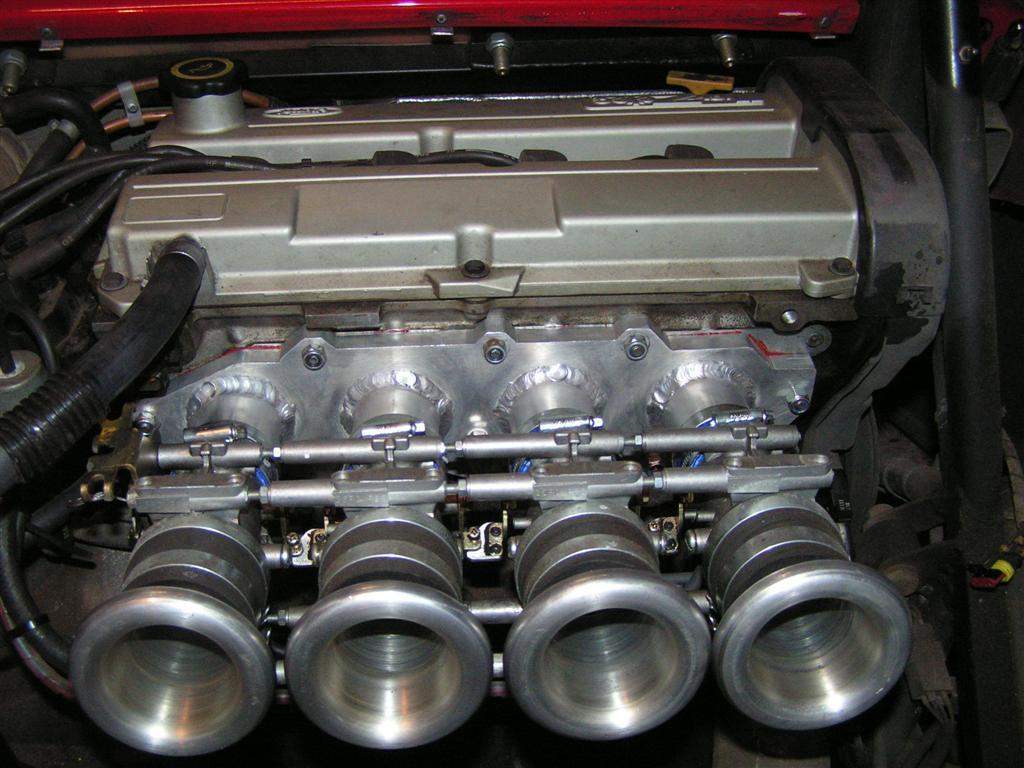
As you can see it has a chunky 15mm manifold plate and 4 neatly welded stubs, which are matched to the internal and external diameter of the GSXR750 throttle bodies. Over the weekend I set to work on swapping the manifold over. This was a fairly easy job. I debated for a while whether to use a Ford gasket or to use some instant gasket. I don't really like using the latter, but the manifold had a few minor scratches that I thought might just cause a tiny air leak. I also offered the manifold up with and without the 4mm thick gasket, and found that if anything the ports lined up better without the gasket in place. The final decider was the fact that the studs I had in my box of bolts were borderline in terms of length even without the gasket in place, so I went for the instant gasket route. The throttle bodies can now sit right up against the manifold stubs, and I conveniently had 4 offcuts of straight Samco hose (the legs off the original 45degree elbows I had bought when I originally did the conversion) in the right diameter to join them up. No other changes were needed, the spacing stayed the same so it was very simple really. Once the instant gasket had gone off, I started the engine up, and it idled fine. I've since done some further mapping with the wideband sensor, and it is now running very well, if anything picking up better from closed throttle than before... More importantly, it looks a lot neater under the bonnet!
Update During Summer 2008 I upgraded my ECU to the Emerald K3 spec. This requires the ECU to be returned to Emerald as there are some minor hardware changes to support the new software. The K3 updates bring a lot of new features, including some things very useful to my setup in particular - self mapping of the injection map using either closed loop or adaptive methods, and load and speed sites that can be spaced to your preference. This meant I could add more load sites down at low throttle openings (it is now setup with sites at 0%, 1%, 2%, 3%... but with wider spacings at high throttle openings). I have also changed the speed sites to 250rpm intervals rather than the standard 500rpm, which has proven most useful around the 1000-2000rpm region. Using the adaptive mapping has enabled the map to be further honed. This essentially logs a corrections table which suggests how the injection map should be modified, but relies on the user plugging in the laptop and applying some or all of the corrections. The car is further improved with the K3 upgrade, well worth the cost of under £40.
|
|||||||||||||||||||||||||||||||||||||||||||||||||||||||||||||||||||||||||||
|
|
|||||||||||||||||||||||||||||||||||||||||||||||||||||||||||||||||||||||||||||


 and new stop (bottom)")