 |
|||||||||||||||||||||||||||||||||||||||
|
|
|
1st December: 3h00m:
Discussing the leaky brakes issue with some fellow builders prompted
me to remove the copper washers between the rear flexi hoses and the
calipers- it seemed likely that the tapers of the two brake fittings were
not being allowed to meet and form a seal. And hurrah, the leaks
went away and so I finished bleeding the brakes successfully.
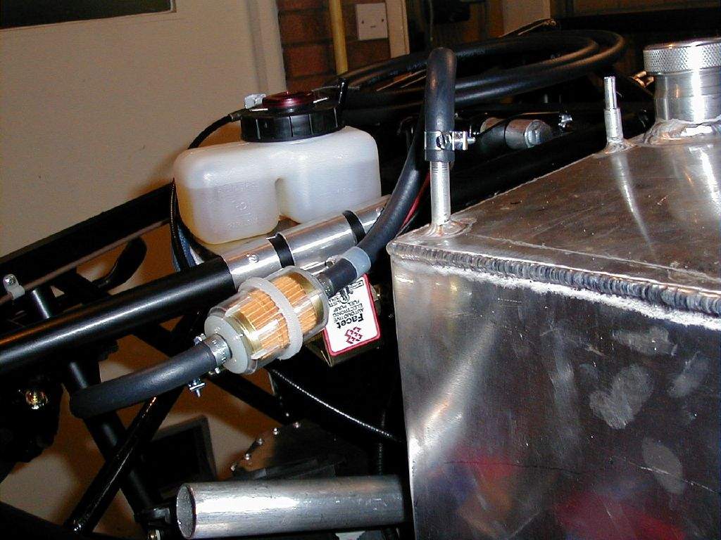
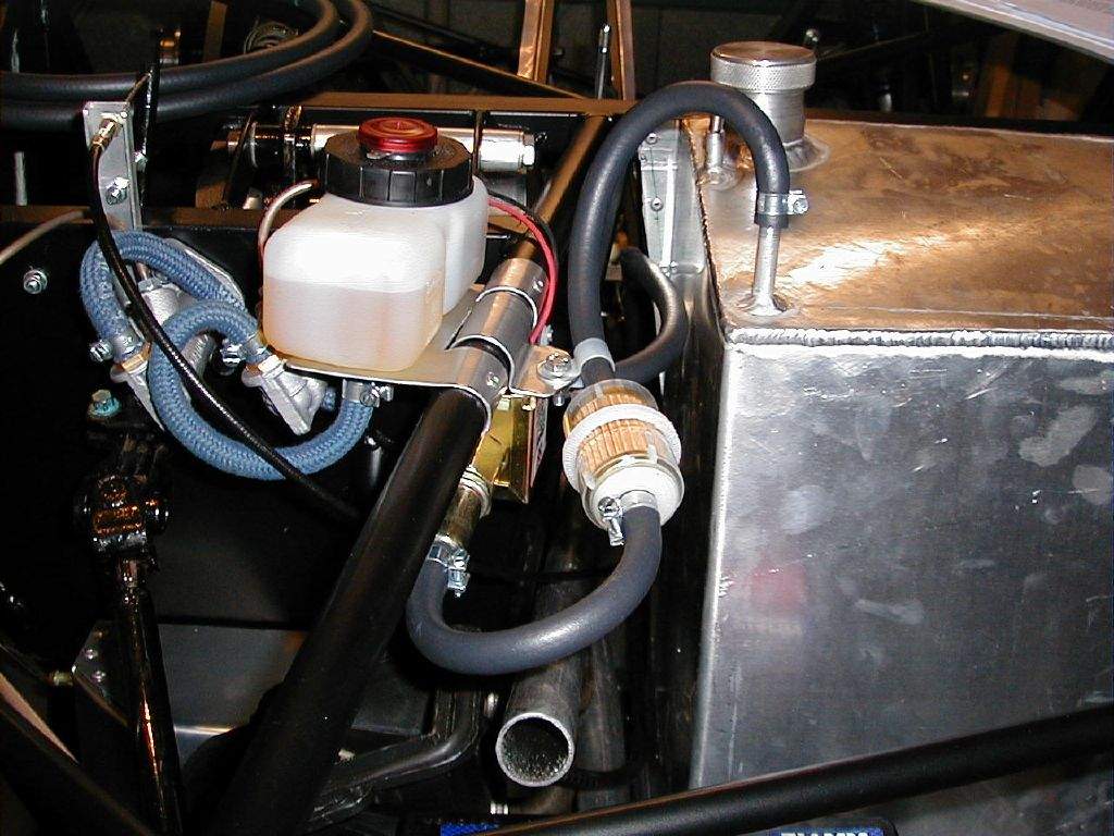
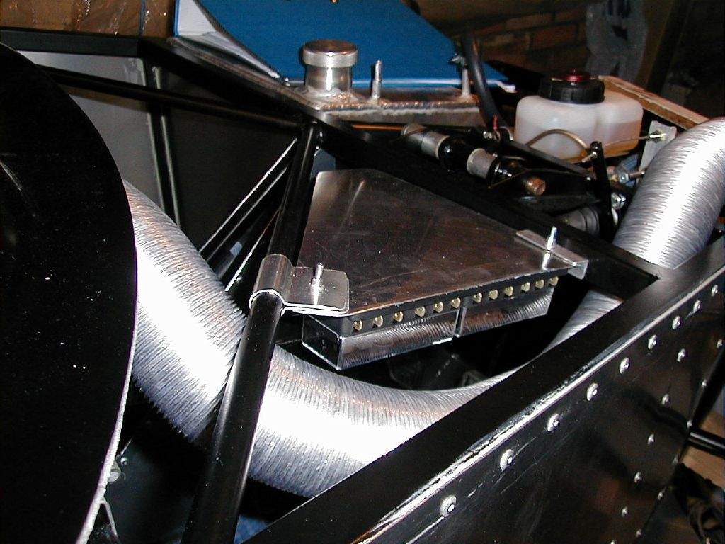
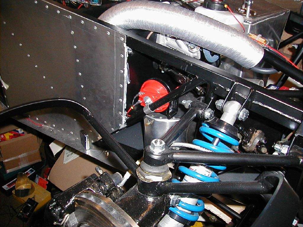
Spent some time trying to decide how to mount the fuel pump. I've gone for a Facet solid state 'fast road' pump as so many people have had bad experiences with the interrupter type. Finding somewhere to mount it neatly was proving challenging though. I finally came up with a plan which mounted the pump upside down beneath the brake fluid reservoir, and began to cut out a suitable bracket. To give some level of isolation between the pump and the chassis, I'm effectively clamping the bracket around the circular chassis member with some bike inner tube in between. This method also saves having to drill more holes in the chassis! 2nd December: 3h30m: Had the day off work today, so made reasonable progress. Finished the fuel pump bracket and then went on to mount the pump and connect all the pipework, including an additional pre-filter just to be on the safe side. I'm pleased with how neatly this has worked out.
Went on to make a securing strap for the battery in its new location.
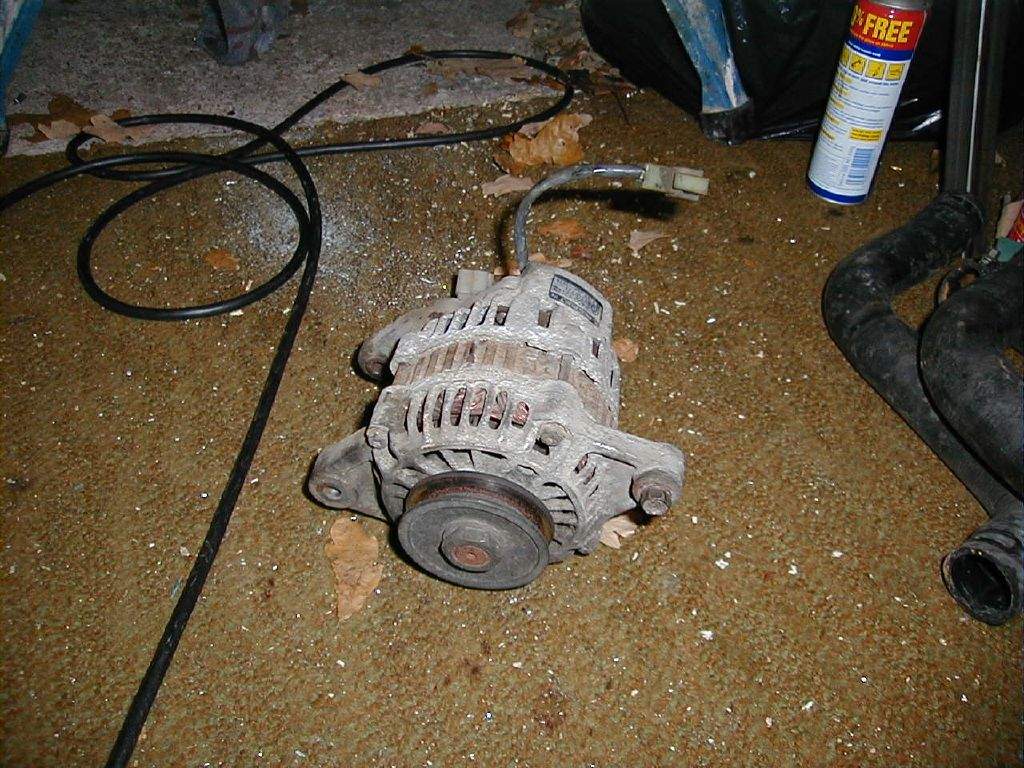
Paid a visit to the scrapyard in the afternoon, and came back with some radiator hose (which may suit the connection between the radiator and the tunnel pipes) and an alternator from a Bedford Rascal! (These are well known for being small and light Japanese alternators, quite a few people have mounted them to Zetecs in the past, I'll just need to make up a suitable mount)
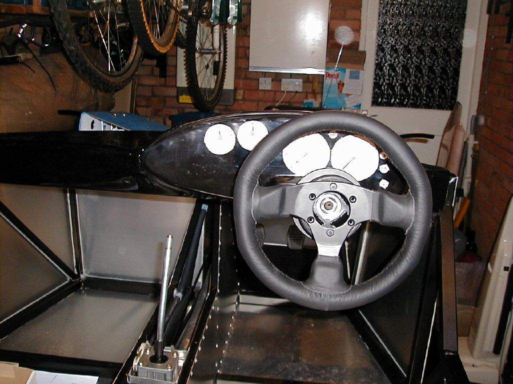
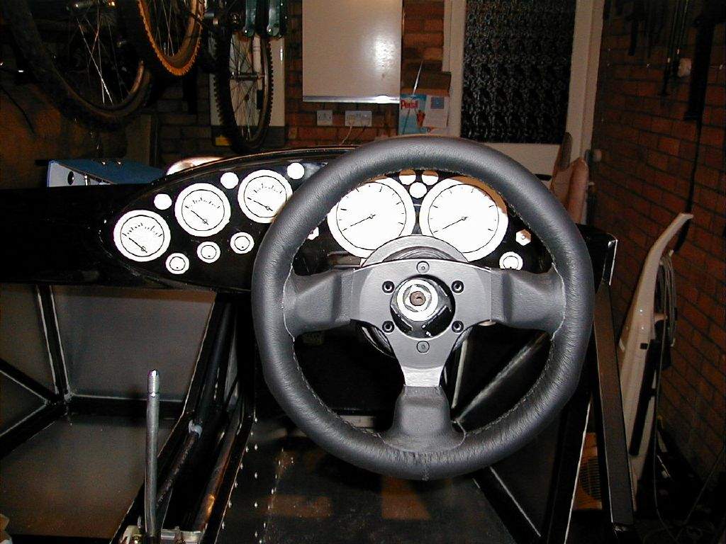
3rd-7th December: 3h00m: Began to think about the wiring in earnest! I've decided to build a loom from scratch, rather than adapting a donor loom or buying a generic loom from Premier Wiring. At first I thought this was mad, but having had some discussions with various kit-car builders (rather strangely, Steve, Steve and Steve... do I know any Steve's who aren't building a kit?) I've decided to go for it. The loom will be bespoke to my car, I'll know it inside out and everything will operate exactly how I want it to. A couple of library books, and some example wiring diagrams off the net (locost7.info & Paul Toynes pages) have given me the information I needed to get drawing my own wiring diagrams. Hence, not a lot has been done in the garage...! 8th December: 0h30m: Bought relays, some aluminium duct and a few other bits and pieces. Trial fitted the ducting along the route from the heater blower to under the dash- I think it'll be fine. 9th-12th December: 3h00m: Not really done any work in the garage, but have been having fun continuing with my wiring diagrams... 13th December: 2h30m: Spent a while making a list of stuff to order from Vehicle Wiring Products on Monday morning. Paid a visit to the bodywork (stored in a friend's garage) to take some measurements to enable me to fit the dashboard in the correct position. Then I began to cut out a section from the dash moulding to fit around the steering column. This is the first cutting and filing of GRP that I've done- be prepared for lots of dust! Didn't have time to finish the fine tuning of the cut-out, another job for tomorrow. 14th December: 3h00m: Continued to cut out the dash around the steering column. The height at which to fit the dash turns out to be mainly dictated by getting the 2 main gauges visible behind the steering wheel. As I'm fairly tall (at 6'2") my line of sight is quite high, which meant fitting the dash on the low side (well, that's what it looks like when compared with the pictures on the Sylva website), but this shouldn't be a problem. With the dash now sat in
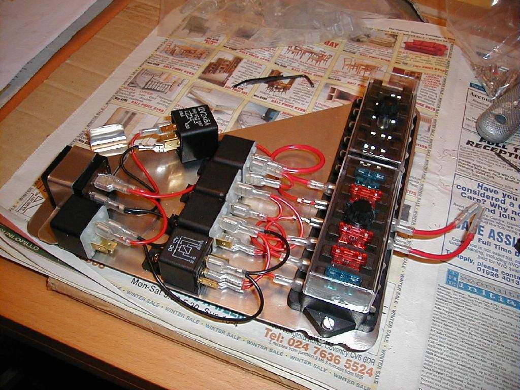
the correct place, I made up 4 securing brackets, 2 per side.
It's easier to look at the photo than for me to describe them!
Once again the rivnut tool was in use to give a means to bolt down
the dash.
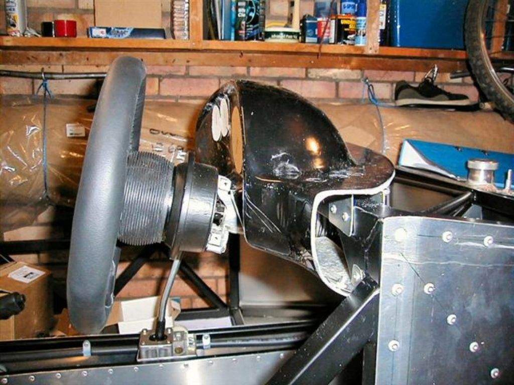
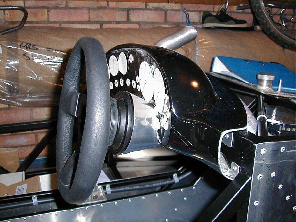
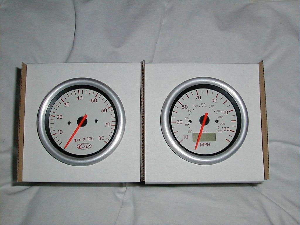
15th December: 2h00m: Ordered a load of wiring stuff from vehicle wiring products, and also ordered my dash instruments. Finalised where and how I was going to mount my fuse box and relays (after giving this a lot of thought for the last few days!), and began making up the brackets and mounting plate. I've decided to locate these above the drivers footwell, with access from inside the car, so that my cable runs from the dash to relays and fuses will be short and (hopefully) neat. The mounting plate will be bolted on using rivnuts, so I'll be able to drop the whole lot down for easier access should any major wiring gremlins set in. 16th December: 1h00m: Too cold to work in the garage so spent some more time scribbling wiring diagram plans. I had been debating whether to use some kind of column stalks to reduce the number of switches on the dash, but I have now decided to go for the true kit car approach and use a combination of toggle and rocker switches. SVA regulations will only allow the use of toggle switches within a specified zone, within a certain radius of the outer edge of the steering wheel. However, because the Mojo dash moulding has a relatively small area for mounting switches, it mostly falls within this zone. See an SVA manual for more details... 17th December: 1h00m: Took some measurements for my planned steering column surround. I want to fill the gap between the Mountney boss and the dash, so a cone shape seems to be the obvious solution. I decided where I wanted the cone to taper to, and then returned to the warmth of the house to draft out a pattern using simultaneous equations and some other maths stuff. The proof of my correct maths will be when the aluminium gets cut out! 18th December: 3h00m: Getting close to finalising my wiring diagrams, so decided it would be good to have an electronic version- easier to read, and easier to make minor modifications to without turning the diagram into a mess (which is what tends to happen with pen and paper based diagrams!). Here's the result: 19th December: 3h00m: Cut out the aluminium sheet for the steering column surround, and then formed into a cone shape and secured with 2 rivets. The pattern I had drawn out included a pessimistic cut out to fit around the lower edge of the dash, which I then had to gradually cut back further until I was happy with the fit. This was a slow process! I then made up a bracket to connect the new surround with the lower two mounting points on the Sierra column- more fiddly stuff. Connected the surround to the bracket with a dome-headed bolt threaded into a rivnut. I'm really pleased with the result - it looks good enough to leave to leave uncovered (I had expected to have to paint it or cover in vinyl). Wiring stuff and dash instruments also arrived:
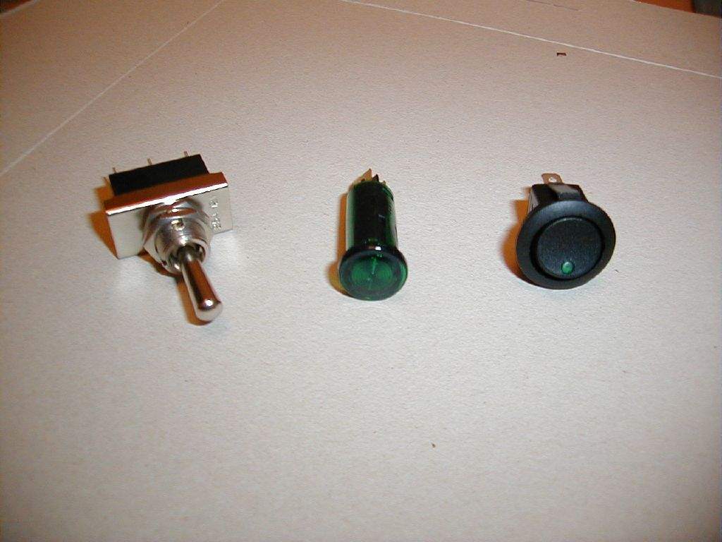
20th December: Bought my switchgear! Here are some samples:
22nd December: 2h30m: Cut out some more accurate templates for the gauges, switches and warning lights, and then had another attempt to fit them all on the dash! The dials are a little larger than expected (90mm &55mm dia) so I'm struggling a bit to fit everything on, whilst keeping everything visible from the driver's seat. The hazard switch has been relegated to the dash top to the right of the main instrument pod. Began to make a mounting strap for the flasher unit, the only one of my relays that doesn't have an integral mounting hole. 23rd December: 2h30m: Began mounting relays onto the mounting plate. Whilst fitting a 4mm rivnut, I broke the mandrel... Hmmm. Had a practice with the crimp tool, it seems to produce good quality crimps. 24th December: 2h30m: Began wiring up relays and fusebox. Since I've mounted these to a removable plate, I could work in the comfort of the house! Also phoned Laser Tools- a replacement rivnut mandrel will be in the post!
29th December: 2h30m: Continued wiring the fusebox / relay board – indoors! 30th December: 2h00m: Finished as much wiring as I could from the comfort of the house, and then mounted the fusebox / relay board onto the chassis. Thought for a long time about my earthing points- where to put them, how to do them? Decided to have a 'front end' earthing point mounted to the upper side of the pedal box, which would serve for all the front lights, fuel pump, heater blower, horn, fuel level sender and all relays. I will then have another earthing point somewhere under the dash for dash back-lights and warning lights, and another earth point (or two) somewhere at the rear. The advantage of using the pedal box panel is it is easy to bolt through from one side to the other, compared with mounting onto a hollow chassis member. I actually used 3 connectors from Vehicle Wiring Products, mounted alongside each other. 31
December: 5h00m: Mounted the horn and
wired back to the fusebox. Spent
some time wondering how to get a cable to the steering wheel mounted horn
push without full lock resulting in a tangled mess- I think a trip to the
scrapyard for the mechanism out of a Sierra or similar may be called for.
Total time spent during December: 40h30m
|
|||||||||||||||||||||||||||||||||||||
|
|
|||||||||||||||||||||||||||||||||||||||