 |
||||||||||||||||||||||||||||||||||||||||||||||||
|
|
|
2nd May: Spent the day at the Stoneleigh show. 6th May: 2h00m: Took the alternator pulley to work in the hope that someone would be able to reduce the thickness of the flange. I had success, although on returning home I found that the recess was now not wide enough to take a socket- which would be rather handy for tightening purposes! 7th May: 3h30m: Had the pulley turned down for the second time, this time with success! Popped into my local Lucas to try and get hold of a nut to hold the pulley on (original had been masacred by the angle grinder during removal...)- they dug one out for me and fitted it with their air powered gizmo, all at no charge- thankyou! Swapped the 25mm angle iron I'd previously bought for the alternator bracket for equivalent 35mm at B&Q- I decided that the 25mm would be a bit borderline once it had 8mm holes drilled in it for the mounting points. Once home, took some measurements and, armed with the angle grinder, cut out the two pieces required, and then made them look nice too!
8th May: 2h30m: Painted the alternator brackets with black Smoothrite, then went shopping for anti-freeze, gearbox oil, alternator belt... Re-routed the heater feed at the rear of the tunnel to try to improve clearance with the gear linkage rod. Brackets were then dry enough to re-fit the alternator and try the belt- too short, doh! Another trip to Halfords tomorrow...
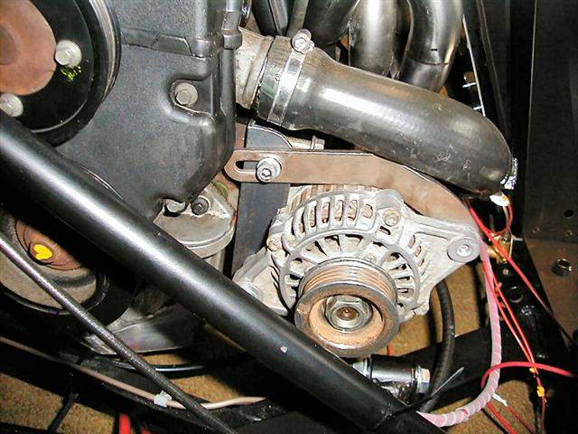
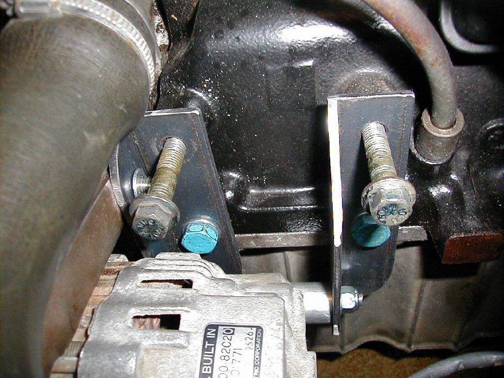
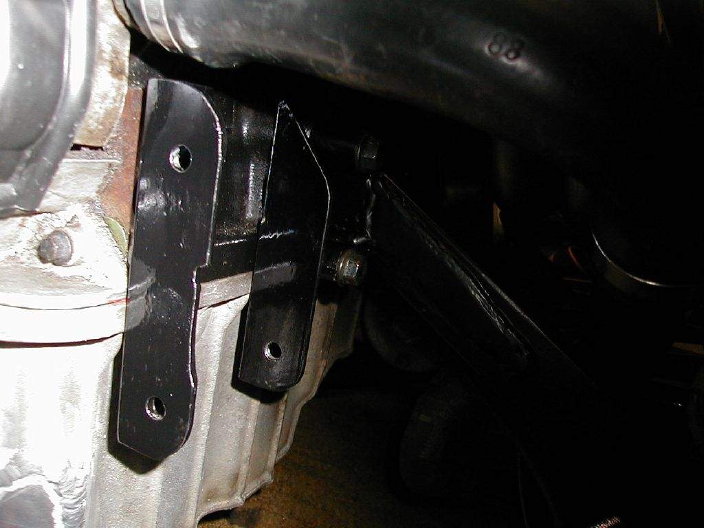
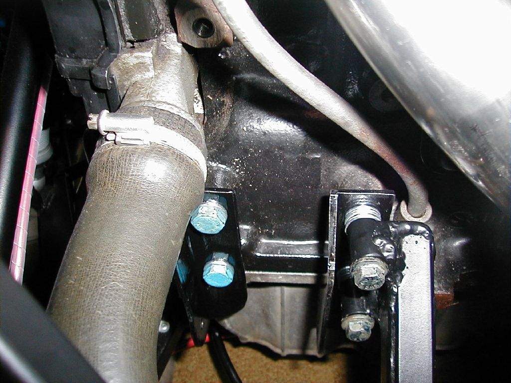
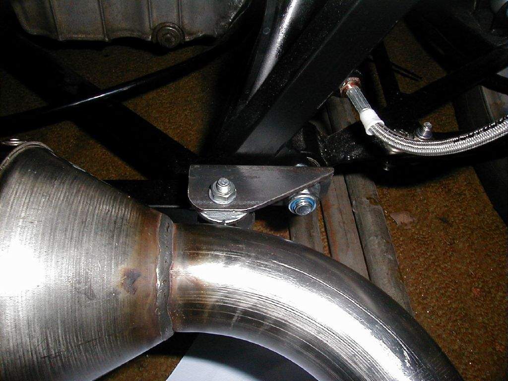
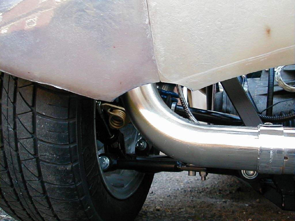
Went round the whole car checking the tightness of all cooling system hose clips. Fitted the bleed hose to the heater matrix. 9th May: 6h00m: Returned to Halfords to get another belt, this time 913mm long (there was nothing in between). Tried this once I got home, hmmmm, too long! But not by much, so I took off the whole alternator bracket again and spaced it off the block with a couple of washers. Thankfully, this was enough, and the belt could be refitted and tensioned! Hurrah! Rob turned up to lend a hand at this point, hoping to be around for the first start up... Mounting the exhaust was the next step. A small piece of the 35mm angle iron was put to use on the right hand side. Most people seem to fit a left hand mount too, but for the time being I'm just doing the one:
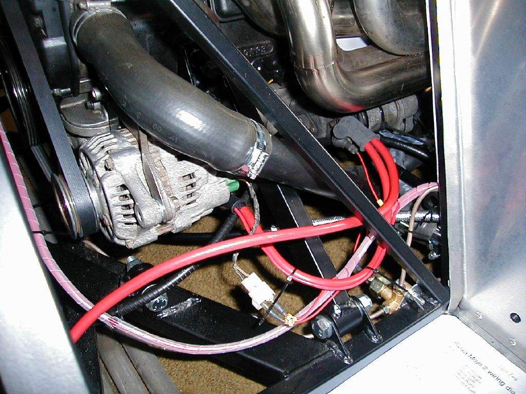
Sorted the wiring to the alternator and starter motor- the wires were in place, just lacking connectors, so this was a quick job.
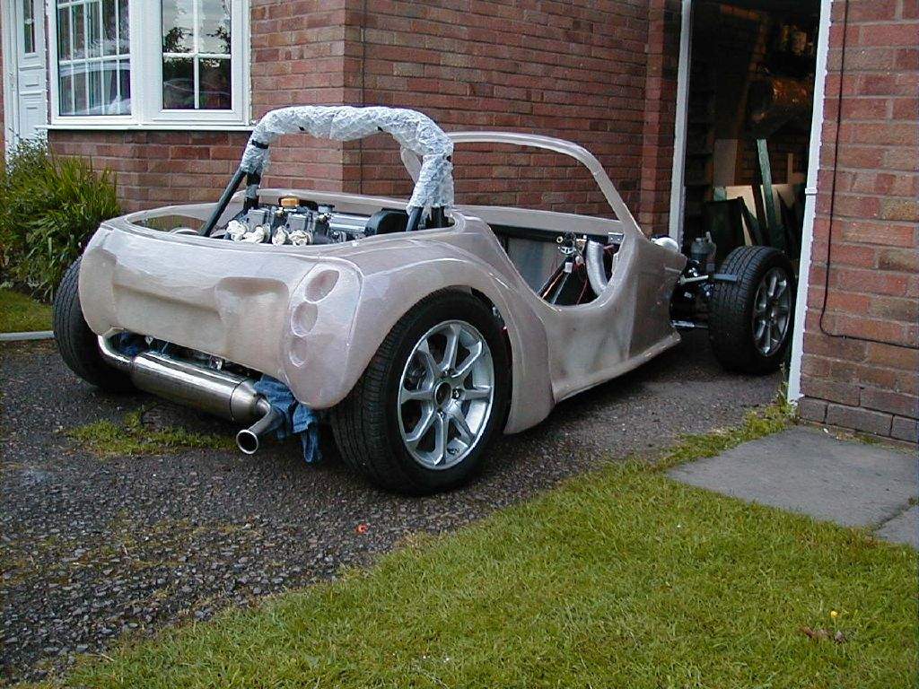
Filled the engine with oil until max was showing on the dipstick- no leaks yet! Put some petrol in the tank. Yikes, this is getting scary!
Filled the cooling system. Well, started to fill it, until water started gushing out of the radiator! I just knew this would happen- when I fitted the rad I said to myself- 'you must remember to do something about the hole in the rad for the fan switch'. Guess who forgot! Unfortunately, there aren't many places open at 6pm on a Sunday, so out came all the boxes of bits, including all the non-car stuff, searching for something to fill the hole. Amazingly, we got something to work- one of the old water temp sensors that was originally in the zetec thermostat and a big rubber washer seemed to do the trick! Everything seemed to be ready, so I went to turn the engine over for the first time, with plugs out and no fuse on the fuel pump supply, to build some oil pressure. Bear in mind that at this point I didn't even know whether the starter motor would work... Thankfully, it did, and the engine cranked away! Oil pressure seemed a bit lacking though, so we tried quite a few more seconds, but still only a slight flicker from the gauge. Hmmm, what next? Well, I decided just to go for it and hope for the best, so stuck the plugs in, put the fuel pump fuse in, and firstly turned on the ignition. The fuel pump kicked in and started picking up fuel. I then went ignition off, then back on and repeated until fuel reached the carbs. Then, finally, I went for the starter again... First time, no sign of the engine catching... second time and we have a couple of pops... third time and we have a small flame out of one of the carbs... fourth time and brrrrrmmmmm she roars into life straight away, oil pressure builds and I'm a happy chap! Left the engine running for a few minutes, watching for leaks, but everything looks OK so far! Idling high at 2500rpm, but that can be tweaked later. 10th May: 1h00m: Ran the engine again, notice that cylinder No.4 exhaust is cooler than the rest, and idle seems a bit lumpy, but then again the carbs need setting up... Backed off the throttle stop to get the idle down, but it won't go below 1500rpm yet. Carbs do need balancing though, so I'm not worried at the moment. 11th May: 1h00m: Ran the engine again, still not especially smooth, but the No.4 exhaust is getting hotter now. Maybe it's a dodgy plug or lead... Decided I would have to change my gear linkage setup slightly. I had wanted to go with a single rod all the way through, but the combination of forwards-backwards motion with side to side motion is giving me clearance problems with some of the cooling system pipework. I will revert to using the original rocker arm, I think this should work OK. 12th May: 2h00m: Ran the engine once more, this time fiddling with the idle mixture screws. The idea is to adjust each in turn to give the highest tickover, then re-adjust the throttle idle adjuster to get the idle speed correct. Something strange is definitely going on with the left hand carb, the idle mixture screws make little difference to engine speed in comparison to the right hand carb, especially on the far left cylinder. Further investigation required... Made a start on changing the gear linkage. A quick bit of angle grinding of the rocker arm was required- the original design needs to change the direction that the gear rod moves in, hence the rocker has a central spindle and a connector for the forward rod above the axis, and a connector for the rearward rod below the axis. Since my gear linkage already moves the rod in the right direction, I removed the top section of the rocker arm, so both the forward and rearward rods will connect to the lower connection on the rocker arm. 13th May: 2h00m: Finished the mods to the gear linkage, which meant drilling 4 holes in the metal bar that acts as a spindle to take 4 split pins. These secure the bar to the chassis, and the rocker arm to the bar. A bit of fine tuning was required to get things working smoothly! A bit of searching on the net earlier in the day had given me some ideas about my carb balancing problems. I had a few possibilities to look into:
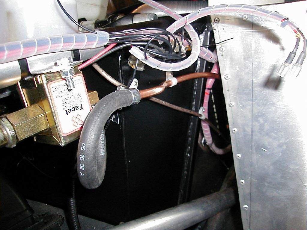
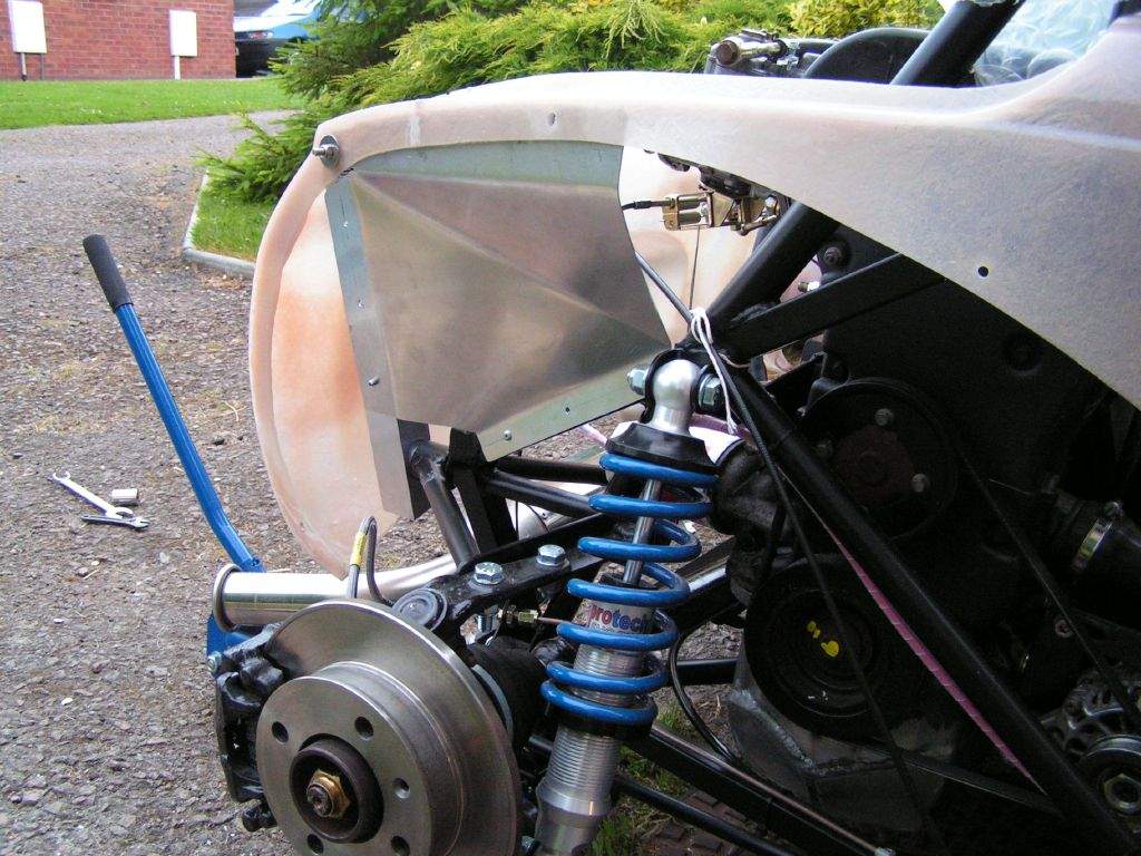
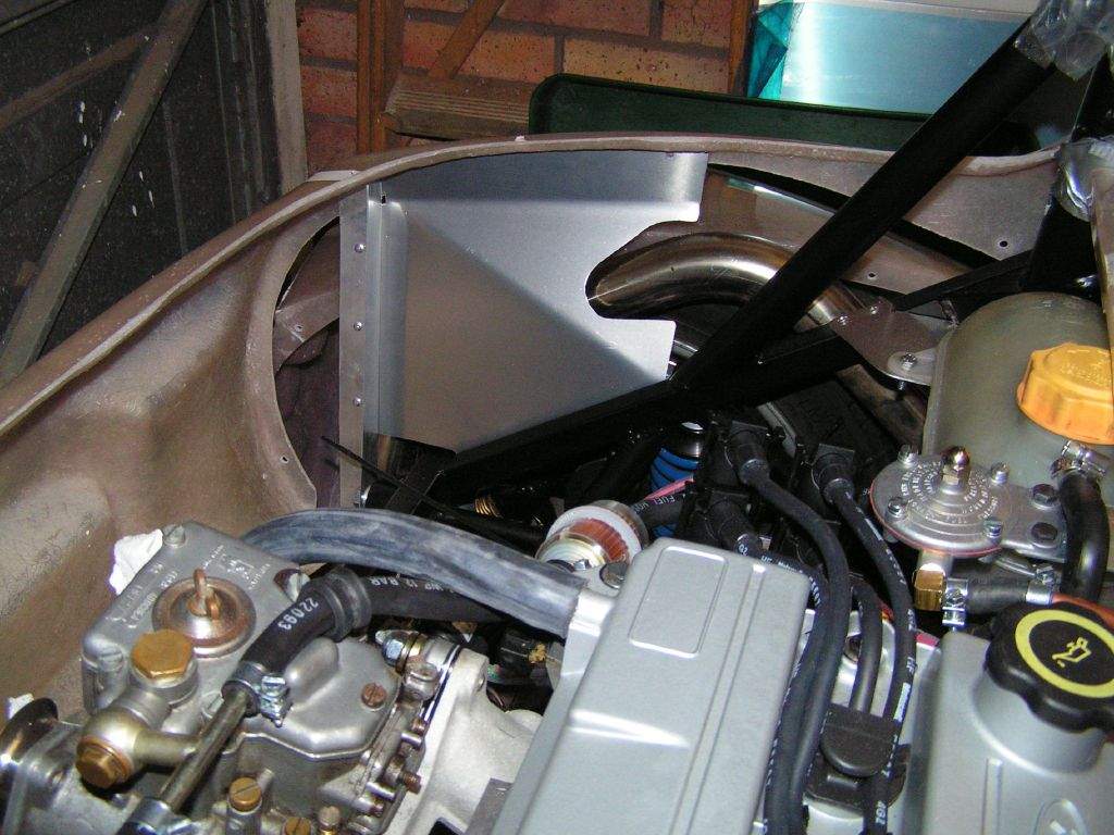
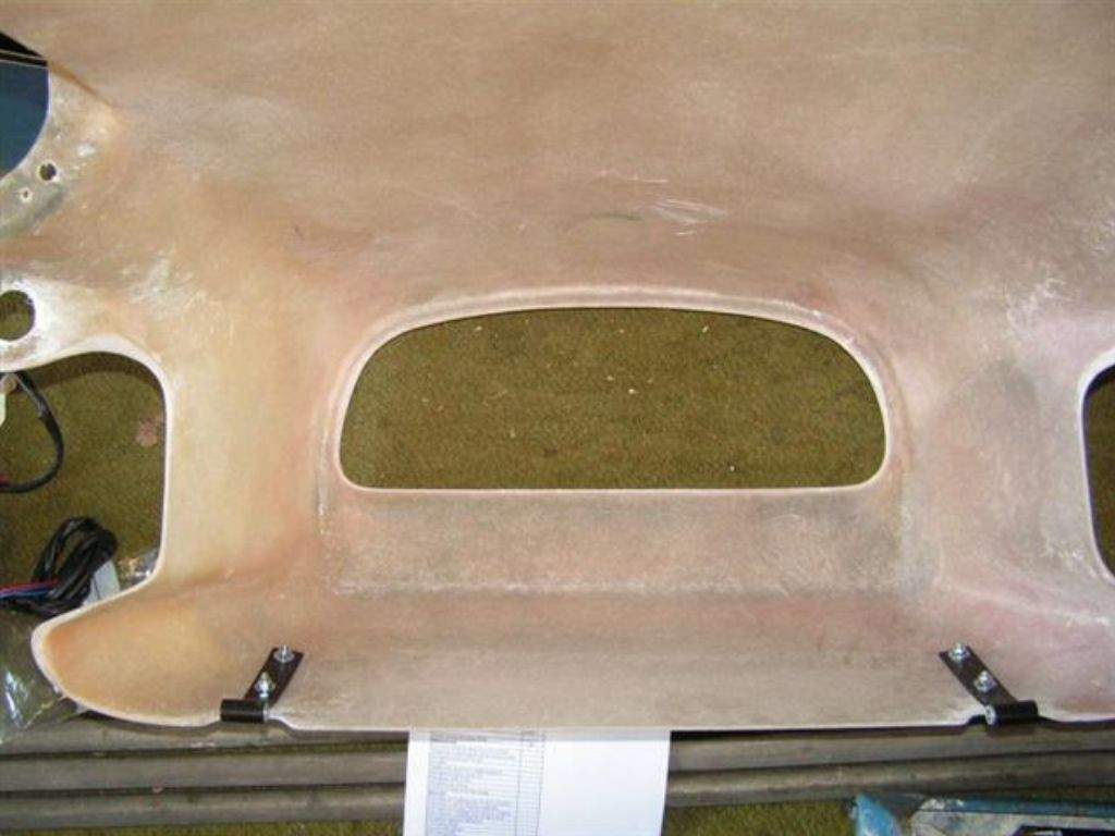
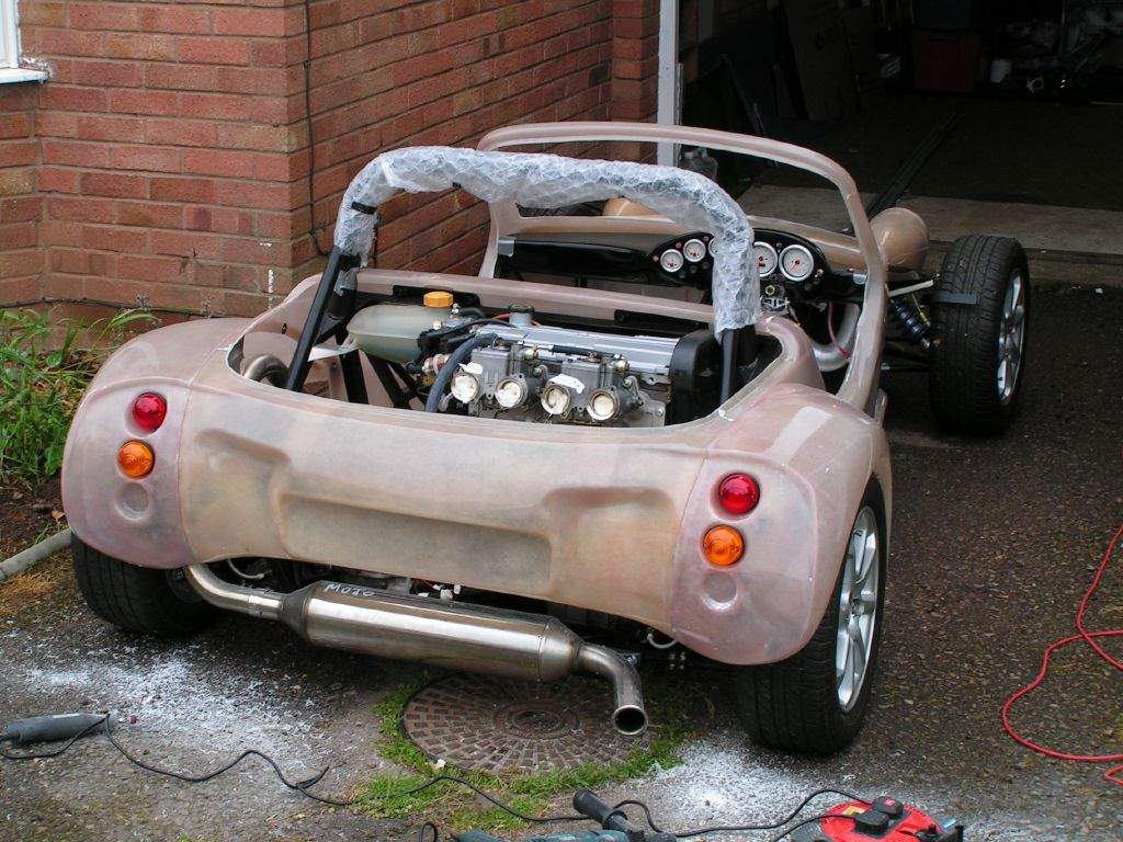
Also, I came across numerous issues relating to zetecs and dodgy plug leads, so decided I would also renew these as a matter of course. As for the carbs, there was only one thing for it- take them back off! I started with the left hand carb, as this was the main problem. Once off, it was indeed possible to see that the far left barrel had a throttle plate that was marginally more closed than the other- I'm only talking maybe 0.5mm at the top edge of the throttle plate, but it was plain to see that the gap around the plate was significantly greater on the right hand barrel. So- one step in the right direction! A bit more research on the net revealed that trying to bend throttle spindles is a bit of a dodgy business- but I thought I had nothing to lose! Out came the big adjustable spanner, and a couple of minutes later I had 2 aligned throttle plates, and no breakages! With the carb off, I noticed something else which could be causing problems. On the face of the carb that faces the manifold were 2 lead plugs that seal off some of the internal passageways of the carb- no big deal. However, these plugs were not flush with the rest of the mounting face, and sat under the sealing O-ring of the MISAB plates- so there was the chance of an air leak! 14th May: 3h15m: Removed the second carb. I have decided to smooth off the lead plugs on the 2 carb mounting faces, and also to block off the 'cold start' circuit completely, to make sure these don't cause any problems. I used some metal filler, hopefully this will do the job... The throttle plates in the second carb were spot on, so no further tweaking was required. While the carbs were off, I also removed a little material from the throttle stop on the left hand carb- previsouly the idle speed could not be adjusted low enough because the stop attached to the spindle was hitting the carb body. Cut out the first piece of heat reflective matting, and attached this to the piece of aluminium that blocks off the rear of the tunnel. This should help stop the ECU getting too toasty! 15th May: 7h30m: Checked that the metal filler I had used on the carbs had hardened sufficiently, and then smoothed the finish with a combination of stanley knife and wet and dry paper. I had noticed that both of my clear fuel filters had minor leaks where the hose was fitted on, so removed both to investigate. It seems that the cheapo plastic filters have ridges from the mould on the connecting nozzles, which were allowing a little fuel to pass. Gentle use of a stanley knife smoothed the nozzles, hopefully this will fix the problem. Reassembled the carbs to the manifold, reset the idle mixture screws to 1 turn out and then fired the engine up again. The trusty piece of hose was used again to listen to each of the trumpets, and this time things sounded more promising- each pair was sucking fairly evenly, with just a difference between the two carbs. I adjusted this with the balance lever between the carbs, until all four trumpets were sucking fairly evenly. Then I backed the idle down to about 1000rpm and rechecked the balance, then moved onto the idle mixture screws again, and followed the procedure I mentioned on 12th May diary entry. This time each idle mixture screw did affect the idle speed, so I'm reassured that things are working as they should. With the mixture screws setup, I found that the idle would now not go below about 1200rpm, even with the idle speed adjuster screw wound all the way out- the hard stop on the carb body needs a little more material removing. I wonder if this issue is related to me using a brand new linkage on a fairly old set of carbs? The other issue I had come across was the engine not settling back to idle after blipping the throttle. I read somewhere that this could be related to the ECU advancing the ignition a little, making the engine hold on to the revs. I plugged in the laptop to the ECU with the engine running, and had a look at the map. There was a 5deg difference between the zero load 1000rpm ignition advance and the zero load 1500rpm advance, so I backed the 1500rpm value down to the same as the 1000rpm site, and low and behold, the revs now drop off quickly. Hoorah for home-mappable ECUs! Now for the bad news- I have used rubber fuel hose throughout, and I noticed that where the hose leaves the upper rear end of the tunnel, 8 inches or so above the exhaust, the hose had turned 'wrinkly' as it curved round and onto the fuel pressure regulator. It feels very weird, as if there are two layers of rubber in the hose construction, and the outer layer has parted company with the inner. I guess the rubber hose doesn't like the heat from the exhaust, I thought it would be far enough away... In fact, further prodding and squeezing of the fuel line elsewhere in the car revealed that, although not 'wrinkly', in most places it felt as though the hose outer sheath had parted company with the inner layer, in both the higher pressure section of the hose (from pump to regulator) and the lower pressure sections. I don't like this, so I'm resigned to replacing the whole lot! I don't know if the fuel hose I bought was 'dodgy', but I will now go for a rigid line down the tunnel and above the exhaust, with a few short lengths of rubber hose to join things together (I'll buy a different brand of hose!). I'd arranged for Rob to come by again, to make use of his Hilux pickup to get the bodywork transported from its storage location in a friend's garage (thanks Rachael!) back to my place. This all went smoothly, and I then made a start on cutting out the main tub to fit around the roll bar. Andy Sayle's website proved useful at this point- thanks for the pictures Andy! A trial fit of the body revealed that the front end of the tub is a very tight fit over the chassis- at the moment I can't actually get it to drop low enough! At this point I called it a day, and left the body sat rather higher than intended:
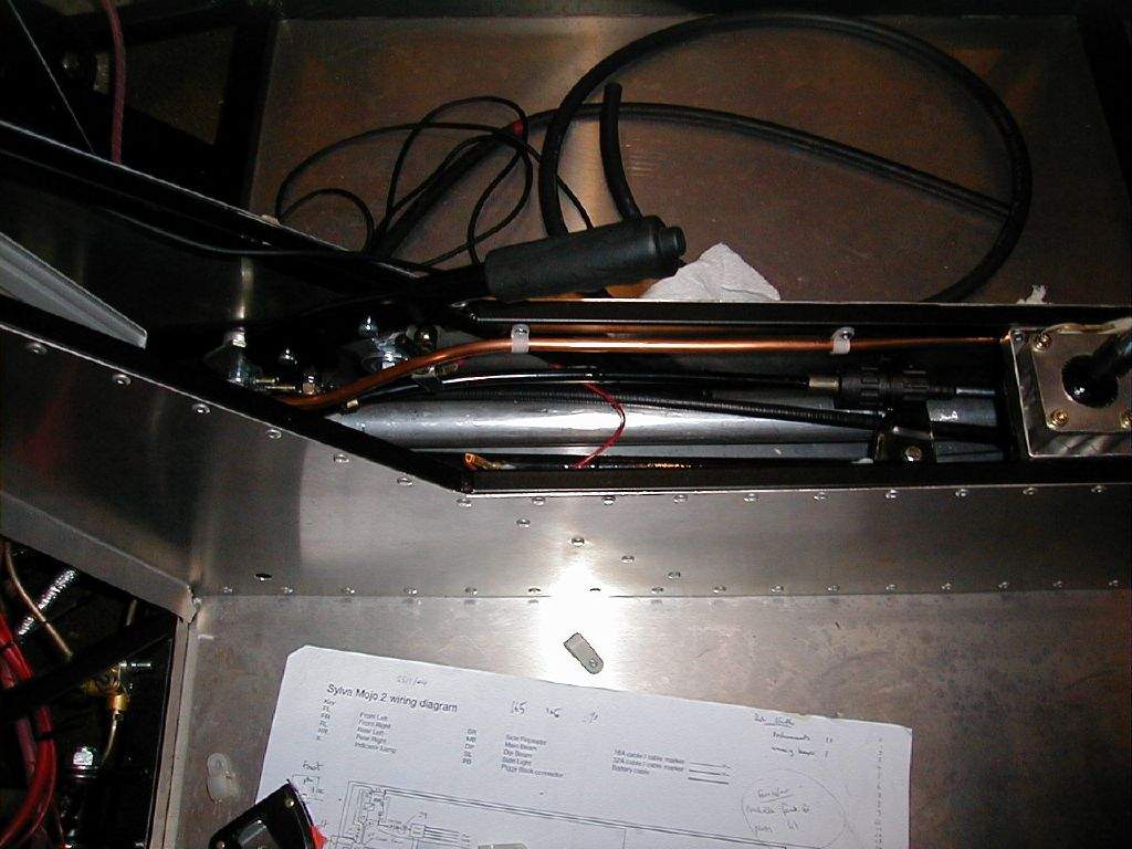
16th May: 1h00m: Went shopping for the replacement fuel lines. Lots of people have used copper microbore central heating pipe as a rigid fuel line, so I went to B&Q. It comes in 8mm and 10mm varieties, so the 8mm is perfect for joining to 5/16" or 7.9mm fuel hose- just under £8 for 10m, which will be more than enough! Also bought 1m of rubber fuel hose (not in B&Q, before people start wondering...), a breather filter for my catch tank setup and some 7.9mm P-clips to secure the rigid fuel line down the tunnel. Once home, I finished tweaking some ECU settings using the laptop, which I had borrowed for a few days (thanks again to Rachel!). I set the radiator fan to come on at 96deg and turn off at 92deg (seemed like a reasonable starting point), and added coolant temp dependant ignition settings to the ignition map (these were just copied across from another zetec base map that came with the ECU). This means that from a cold start, the engine is given some additional ignition advance to help it to run- this should mean it requires less 'nursing' on the throttle for the first few minutes. I then had a quick look at the catch tank setup, which will use a 'Sigg' type aluminium water container. I will plumb the cam cover breather into the top of the bottle (15.8mm heater hose), and then use 2 spare fuel unions tapped into the side of the bottle to attach the crank case breather (8mm fuel hose) and the breather filter. 17th May: 0h45m: Made a start on removing the fuel hose from the tunnel. The P-clips were removed by shearing through the rivets, a quick tap with a hammer on the end of a screw driver did the trick- a bit vicious, but it works... Removed the fuel tank again, now I just need to drain the fuel out of the fuel line... 18th May: 0h30m: Drained the fuel out of the lines, and then pulled the rest of the flexible hose out of the car. 19th May: 2h00m: Fitted the new copper fuel line, which was a bit of a pain with the engine in place, but I got there in the end. The solid line now runs all the way to the pressure regulator, with just a short 2" piece of flexible hose required to join to the union. P-clipped this in place, thankfully using the same holes as I had drilled previously, with 2 exceptions where I physically couldn't get the rivetter anywhere near the hole. I'll block these up with some sealant and a 'fake' rivet (ie a rivet that I just poke in the hole, rather than rivetting in the hole!)
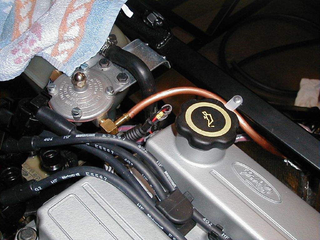
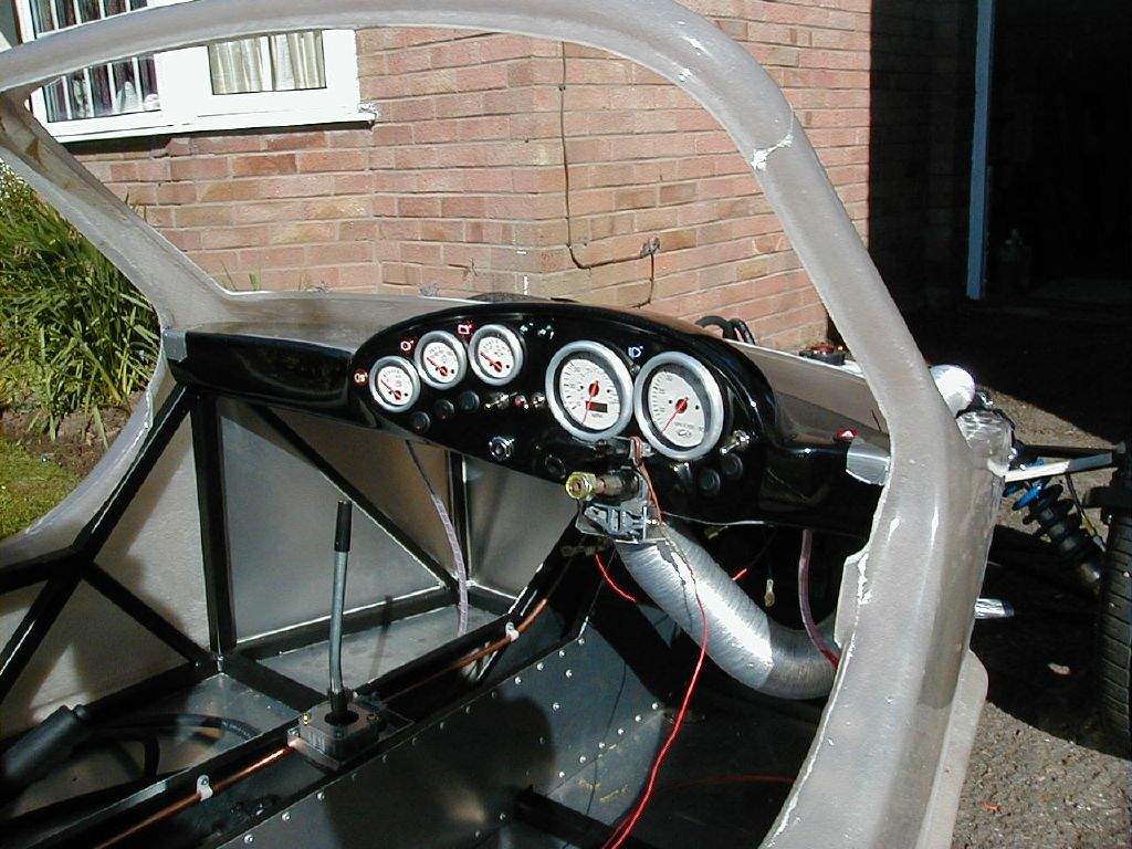
20th May: 2h30m: Fitted the new flexible fuel line from the pressure regulator to the carbs, and from the tank to the fuel pump. The final job was to refit the unions to the pressure regulator, and just my luck, the casing of the regulator cracked as I tightened the union! Aaaaagh! On the phone to Burtons tomorrow then... Realising that the engine wouldn't now be running again for a little while (a fuel supply tends to help...), I decided to remove the dash to assist with fitting the main tub. 21st May: 5h00m: New pressure regulator is in the post from Burtons, I'm sending mine back for them to assess whether it was faulty, or I just gave it too much welly... With the dash removed, I had another go at fitting the tub. This is tricky as a one man operation, but with plenty of rags in key locations on the car to prevent the powder coat being massacred, it was possible. This time, the tub went almost into place, but I could see that I still needed to remove a good chunk from the roll bar cutouts to get the tub far enough back. Off it comes again... I had also noticed a slight clash with the chassis on the right hand side at the very front of the tub, so modified this at the same time as cutting out more material to clear the roll bar. To be careful, I erred on the side of caution which inevitably meant putting the tub on, and removing it again, quite a few times!
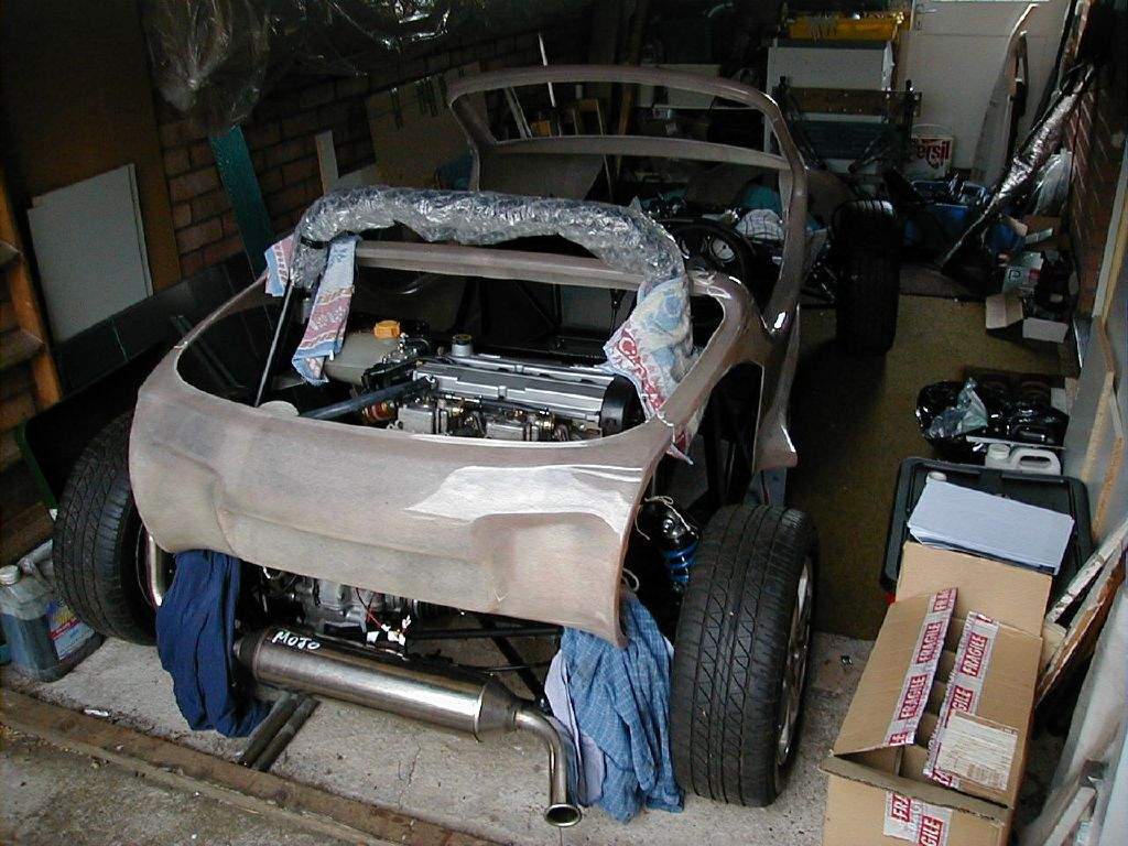
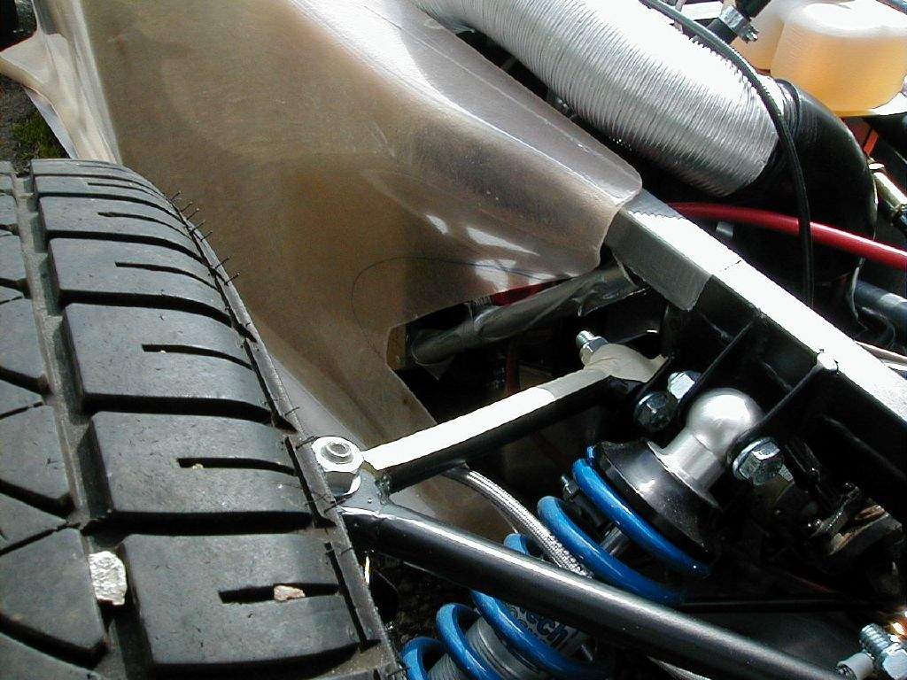
Eventually, I was happy with the fit, so removed the tub once more and then started on fitting the right hand rear wing. This is bolted to the main tub along the jointing flange, I clamped the two parts together to give the correct fit before drilling through. Refitting the tub to the car and then fitting the wing resulted in this:
Intermittent showers meant I had to keep returning to the garage, so during these periods I spiral wrapped the wiring behind the dash, while it was removed, and fixed the missing earth to the main beam warning light, and also the power feed to the shift light, which I also realised I had missed! 22nd May: 4h30m: Re-fitted the dashboard to see whether it, or the main tub, would need any material removing for a good fit. Although a bit of a squeeze, it went straight in, and the face of the dash is just flush with the tub at the base of the screen pillars- my measurements from a few months back were correct! Getting the dash in properly (all wired up etc) is going to be a 'fun' exercise with the tub in place...
Took the dash back out again and stored somewhere safe (on the bed in the spare bedroom...). Made a start on the left hand rear wing, clamping into position and then drilling mounting holes through the flange and into the main tub. The fit at the very front edge of the wing, just below the air intake, had to be fettled again to get it spot on. All of this procedure was done with the tub off the car, which was tucked up in the garage to avoid it getting covered in fibreglass dust- nasty stuff by the way, I wore a dust mask, goggles and a protective 'suit'- very tasteful! Put the tub back on the car, and then offered up the left rear wing to mark out the cut out for the exhaust. Took the tub back off again, and cut out the shape in the tub and the wing. Refitted, checked, removed, re-fettled, refitted, and this time I'm happy with it! I'm getting quite good at getting the tub on and off single-handedly now!
Made some modifications to the tub at the front end of the 'door' opening, just below the base of the screen pillars. I didn't like the way the flanges had been moulded, so took them off... Not sure whether I'll use fibreglass or filler to reform the shape, I'll cross that bridge when I come to it! Bought some 20mm aluminium angle section to fit to the side chassis rails to act as a locator for the main tub- as directed in the build manual. Rivetted this in place, and it seems to do the job OK, but has forced the sides of the tub in a bit further than I wanted. I think a bit of bending of the aluminium bracket should see it sorted! Had a long think about how to support the rear of the tub. Not sure whether to use JP's latest method, with some angle aluminium bolted with the upper wishbone bolt, or to fabricate something more solid. I think I'll try the easy way first. 24th May: 1h15m: New fuel pressure regulator arrived from Burtons, so fitted that back into the fuel line, taking care not to over-tighten! Pondered some more the issue of supporting the back edge of the main tub, came up with a plan, and started cutting out cardboard templates to see if I thought it would work. 25th May: 1h45m: Started making up a bracket for the rear of the tub based on yesterday's cardboard template. It did all fit together, but I wasn't happy with the level of support it was giving- things were still a bit flexible. Hmmm, this might be back to the drawing board... 26th May: 2h45m: Came up with Plan B, and beavered away for a few hours coming up with the new support. This was made with a combination of 35mm aluminium angle and a piece of aluminium sheet with quite a few folds to form the correct shape. It's a bit difficult to describe, so here's a picture:
27th May: 3h00m: Made up the left hand side support bracket for the rear of the tub. This was easy in one respect, in that I had made up a template from the right hand side, but was complicated by the fact that I had to make a cut out around the exhaust. I got there in the end, and I'm really pleased with the result.
28th May: 3h00m: I had deliberately cut the two sections of aluminium angle used to support the upper surface of the rear tub to a longer length than needed, so that they sat a couple of inches below the upper wishbone bolts. This was to enable a small bracket to be joined at each side to support the lower rear edge of the tub. This was a bit of a fiddle, and I had to design two different brackets for each side, due to the cut out in the bodywork around the exhaust. I then bolted the rear wings back on again to check that the rear section of the body was sitting centrally, and at a similar height on both sides. I noticed that I need to drill some more fixing holes between the tub and wings, as the flexibility of the fibreglass is allowing for a variable gap between the panels. More nuts and bolts should do the trick! Began to have a look at fitting the nose moulding. First job was to get the nose to sit in the right place. Now that the main tub was in place, I had a guide as to how far back the nose needed to go. I had to remove a fair amount of the moulding (just below the indicator 'pod') around the upper wishbone mounts, in order to allow the nose to move further rearwards, to give the correct fit at the base of the windscreen. Next, I had to decide how to attach the metal brackets (which pivot about a mount on the front of the chassis) to the nose section, principally whether to mount them inside or outside the nose. One of the brackets had been made with a towing eye of sorts, indicating that the brackets should be fitted outside the nose. However, a trial fit indicated that if anything I would have to space the nose downwards from the bracket mounts, meaning fitting the brackets inside the nose- making the towing eye somewhat useless! After a quick ponder, I decided I was a little uncomfortable at the thought of towing the car using this eye anyway, as it would tend to try and rotate the nose, so promptly hacked it off, and fitted the brackets inside the nose. After a trial fit, I then added a small bend to the mount brackets to get the front of the nose slightly lower, and performed a few more tweaks to improve the general alignment. It isn't perfectly symmetrical, but kit cars never are!
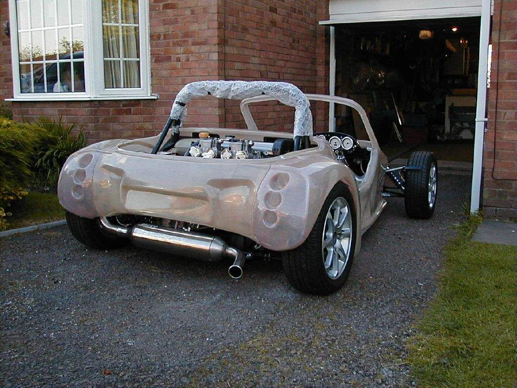
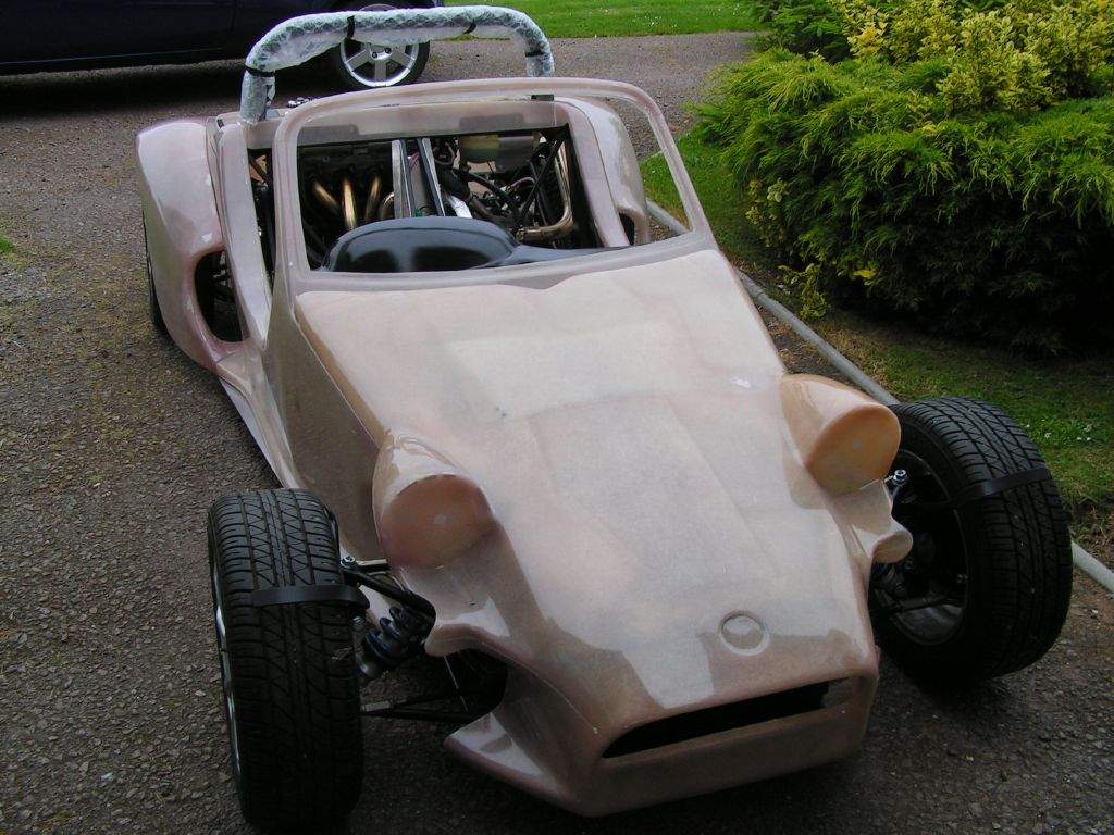
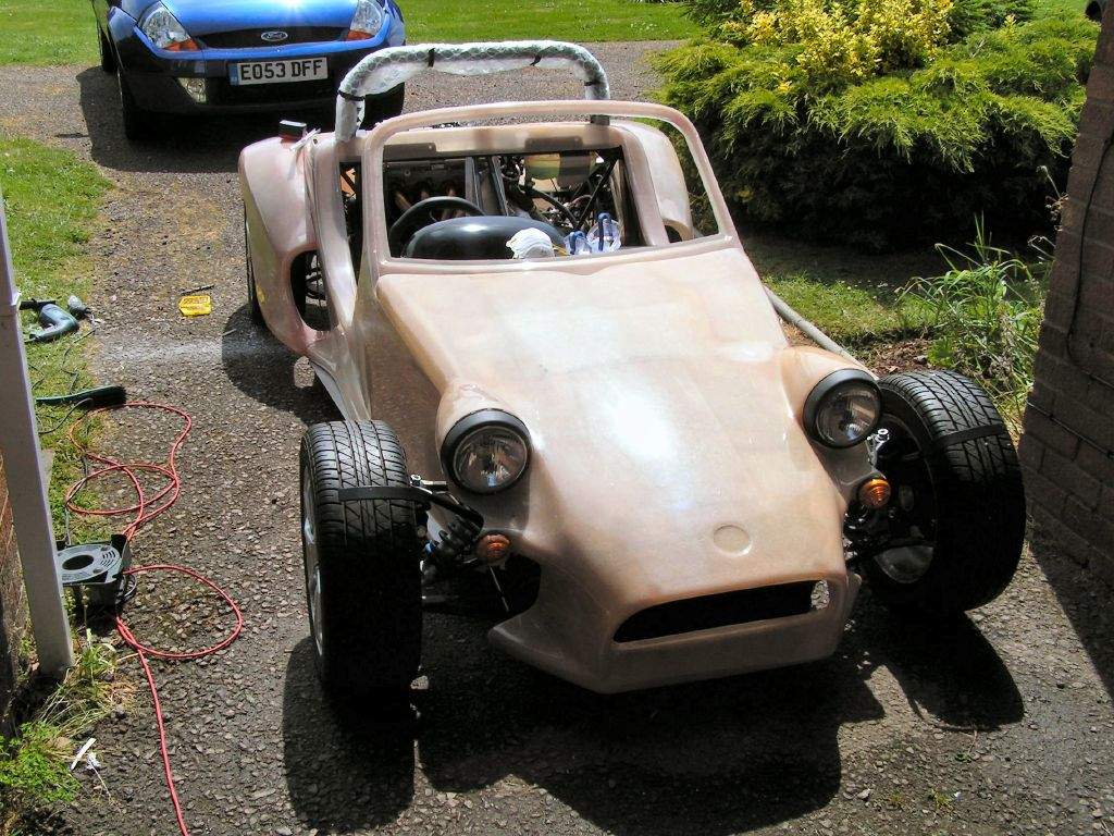
Cut out the holes for the headlights, and fitted them in place with self tapping screws. I don't know if this is the usual way of fixing, self tappers into fibreglass sounds a bit dodgy to me, so I will investigate further... Update: I later changed plan and used button headed bolts and nyloc nuts to attach all of the lights. 29th May: 2h30m: Cut out the central holes for the 4 rear lights and the 2 front indicators. I did this by chain drilling and then using a mini sanding disc on the dremel tool. It's amazing how different the car looks with lights fitted:
Total time spent during May: 61h15m
|
||||||||||||||||||||||||||||||||||||||||||||||
|
|
||||||||||||||||||||||||||||||||||||||||||||||||