 |
||||||||||||||||||||||||||||||||||||||||||
|
|
|
1st March: 1h00m: Ordered some dashboard vents for my heater. I decided a while ago on a general plan for how I was going to do this: -Heater duct runs to centre of car under the dash into an enclosed 'box' -2 vents attached to the top of the 'box' poke through the top surface of the dash for demist -2 further vents attached to the bottom surface of the 'box' for some footwell heating to keep my tootsies warm in winter! I wanted to use vents that could be closed off individually to give some control over the distribution of air, and I like the eyeball-type vents as used on the mk2 Punto and Ford Ka. These were quite pricey to source, plus could prove difficult to mount, and were a bit large for the dinky Mojo dashboard. I spotted the nfauto ones, phoned to check they could be closed off, and ordered 4 on the spot (after taking a deep breath at the £44 total!) Remembered that I hadn't yet changed the oil seals where the driveshafts come out of the differential casing (I bought the new parts months ago). These are part metal, part rubber, the metal outer section being a push fit in the housing, and the inner rubber section forming the seal to the driveshaft. In the Haynes manual it says something like 'Do not be surprised if you have to exert a large amount of force to remove the seals'. Tell me about it! Taking care not to damage anything other than the oil seal itself, I used screwdrivers, hammers, chisels… you name it. Eventually, after about 45 minutes of faffing, the right hand seal came out, but the left hand side is more recessed into the housing, so I decided a crowbar was required. Something else to add to the shopping list… 2nd March: 1h00m: Desperate measures- I went to Homebase for a crowbar! This did the trick on the left hand oil seal, which was removed within about 10 minutes. Phew! Decided it was time to mate the engine and gearbox together. I changed the clutch release bearing (this came in the 'clutch kit' from Ford) and then offered the gearbox up to the engine, lined up the bolt holes and torqued up the bolts. Easy!
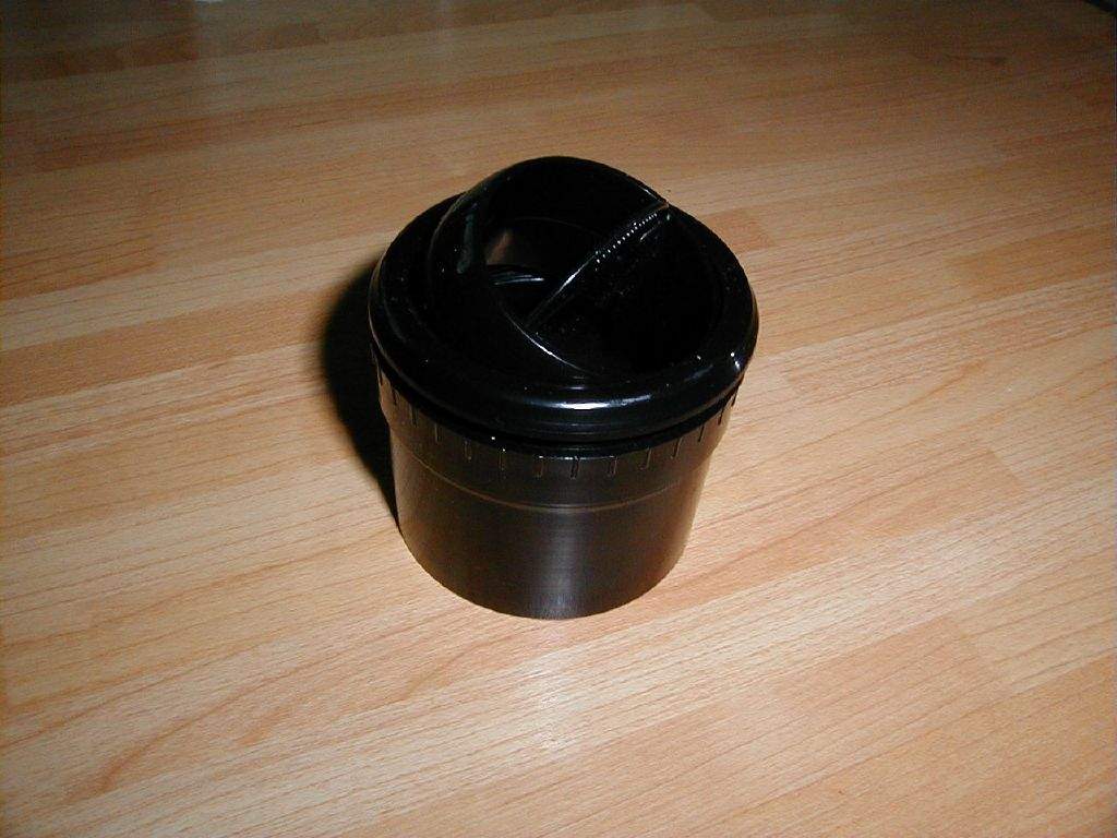
4th March: 1h00m: I had arranged to borrow an engine crane from a local Sylva-chat subscriber, but that fell through when my Leon started running on 3 cylinders on the way home from work! I guessed it was a coil pack failure, a known weakness on the 1.8 VW engine. Heater vents arrived from nfauto- I'm very pleased with them, smaller than an 'average' dash vent, which fits in well with the small dash area I've got to play with, and nicely designed. Rotating the eyeball 90° effectively closes the vent off, so I can choose to have just the demist vents open, just the footwell vents open, or all open at once.
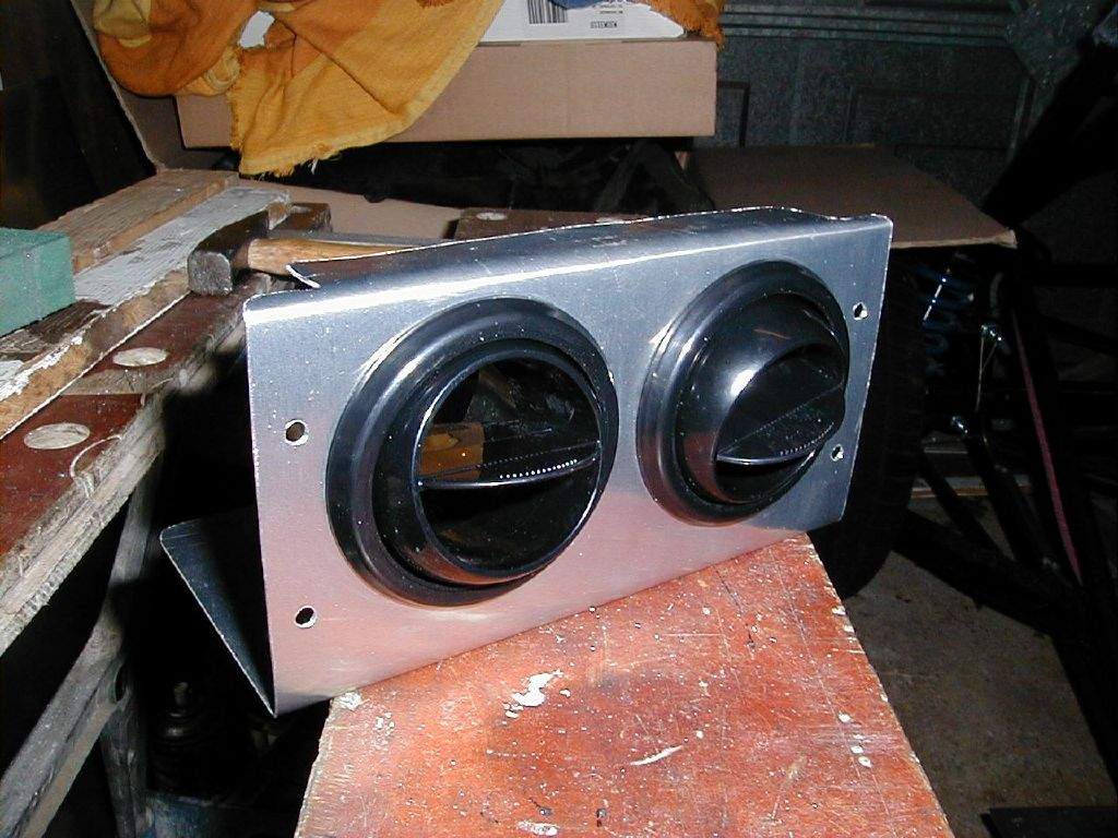
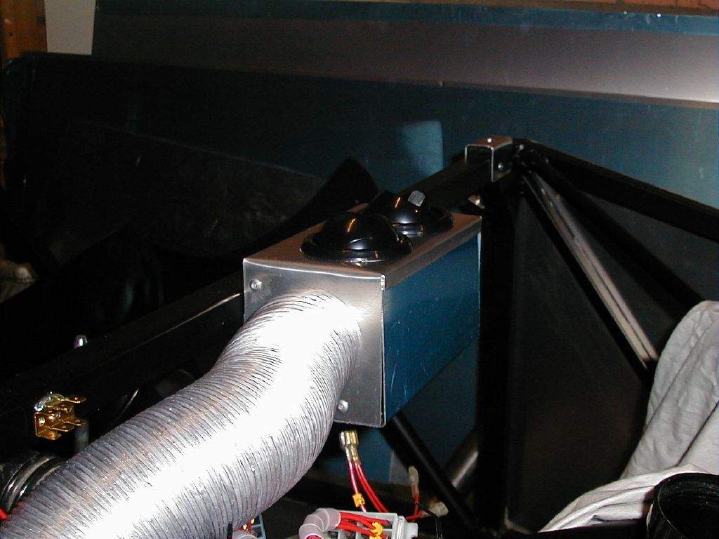
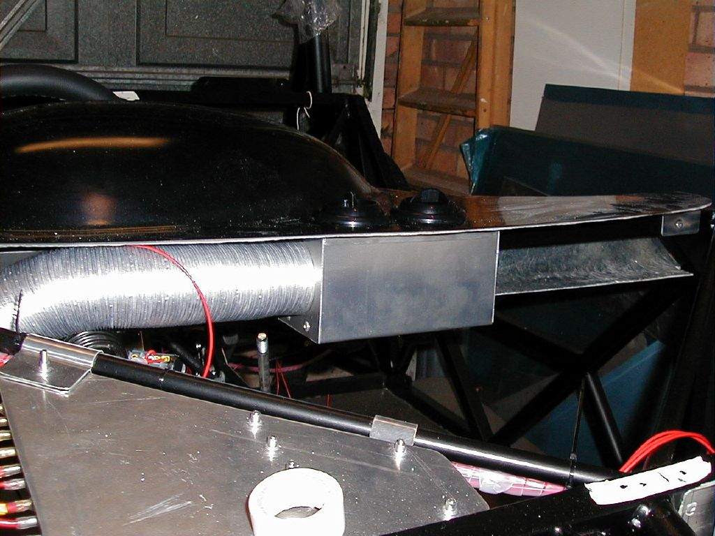
Stuck some white tape to the top of the dash and played around, deciding where to mount the vents on the top of the dash… 5th March: Bought a new ignition coil from SEAT, which thankfully fixed the problem with the Leon. Trip to the scrapyard for a few bits of radiator hose, plus a few other bits and pieces. 7th March: 1h00m: Started to think about how exactly to fit the heater vents. I am going to have to fabricate some kind of box that connects together the duct and the four vents. I also want to use the box as the central support for the underside of the dash- I cunningly planned this a while ago! Didn't come up with a design that I was happy with… 8th March: 3h00m: Pondered some more how to construct the box to connect the end of the aluminium heater duct to the four vents. Finally came up with a design I was happy with, so out came the jigsaw after scribbling some dimensions onto my sketch diagram. The box has to be made in two sections as the air vents secure with a threaded collar that will be mounted inside the box So, my aluminium folding skills were tested again, making up the two halves of the box. This will then have 5 holes cut into it- 2 on the top surface for the demist vents, 2 on the bottom surface for the footwell vents, and one on the right hand side for the heater duct inlet. The design is not going to be particularly elegant in terms of nice smooth ducts to each vent, but I think it should do the trick, and seems to be a very simple way of getting a 4 vent system fitted in a very small space. 9th March: 1h45m: Continued with the vents! Cut the two holes in the top of the dashboard, and marked and cut out the holes in the distribution box.
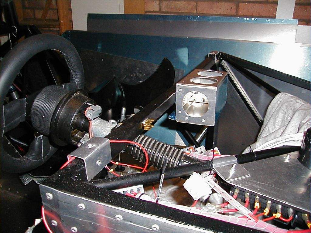
10th March: 2h00m: Finished the heater vents! The pictures should tell the story:
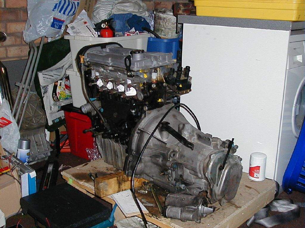
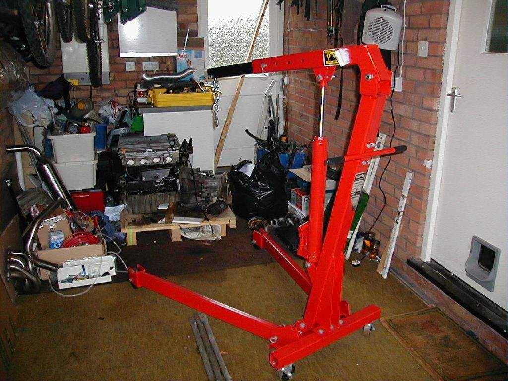
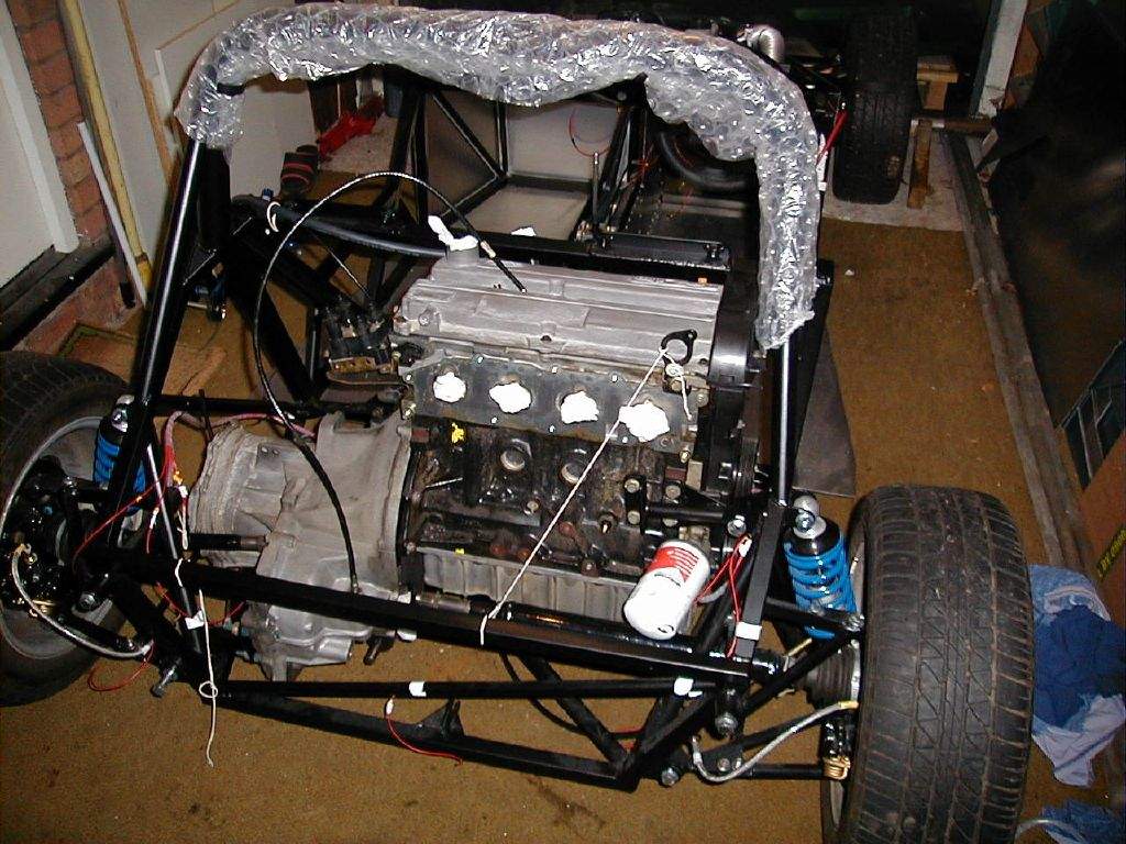
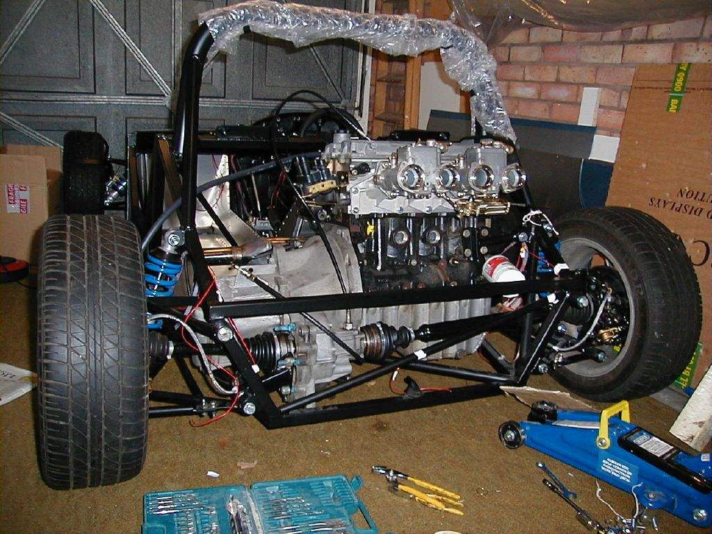
11th March: 2h15m: Thought I ought to try and do some more work on the front end plumbing before putting the engine in. The outlet to the heater matrix is to be T'd into the radiator bottom hose at the front end of the car- I had found a suitable T-piece at the scrapyard last week. A single 90 degree jointing piece had things connected up. Popped over to Leamington to collect the hoist very kindly offered to me on short term load by yet another Stephen! Where do they all come from? Should I be called Steve? 12th March: 5h30m: Decided to go ahead with the plan to get the engine in! After a major garage clear up, my extra pair of hands arrived (attached to Steve!). Set up the hoist (it's one of these folding ones, very impressive!) and then used the engine straps borrowed from work to lift the engine using the lifting points on the head.
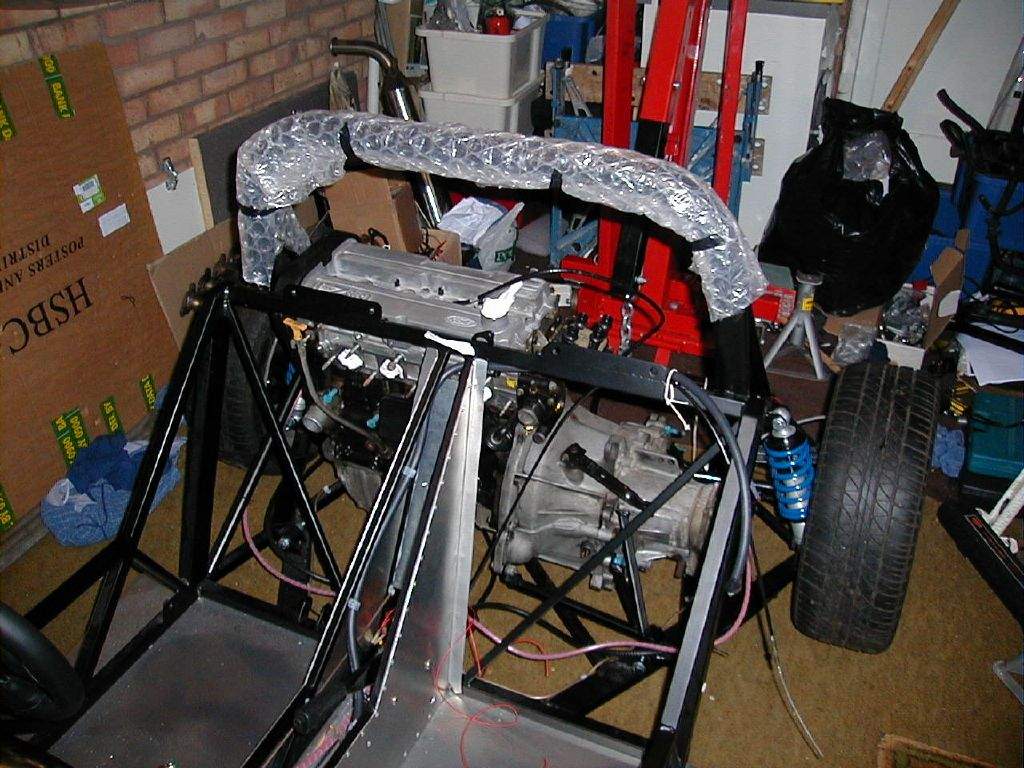
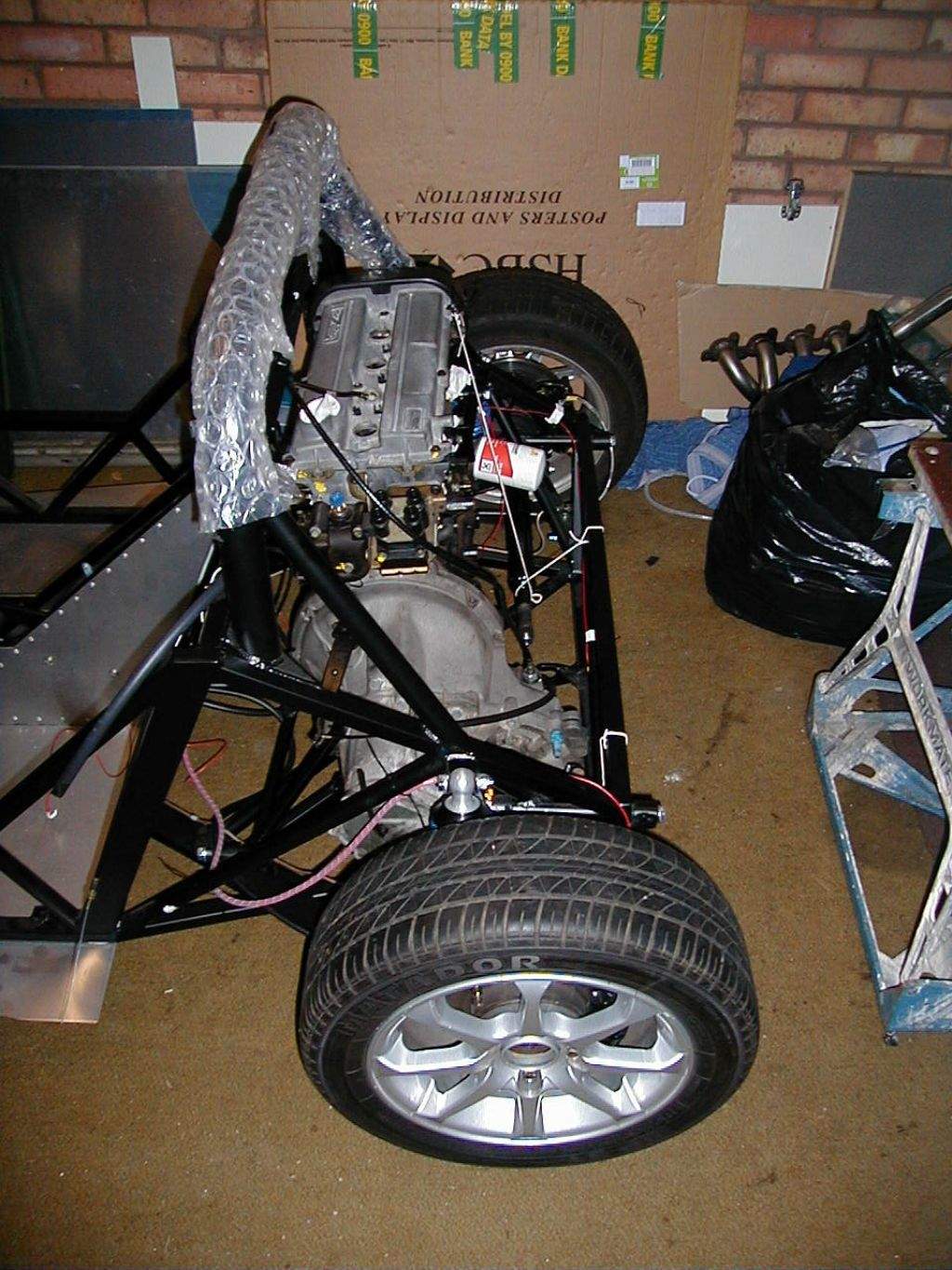
I gave the underneath of the gearbox a quick clean with gunk whilst it was dangling in the air. The Mojo was turned around so the rear end was towards the back of the garage, so the hoist and engine was turned around to see how things lined up. Unfortunately the legs of the hoist were too chunky to slide under the chassis, so the rear of the Mojo was rolled up some ramps. This gave the clearance under the chassis, and thankfully the hoist had enough lift (and the garage roof enough height!) to still get the engine high enough. I had been warned by Steve Knee that he had squashed a brake pipe when putting his engine in, so I did a bit of careful re-routing of the left hand pipe (not too easy given that it is p-clipped in place and full of fluid!) The left rear suspension was also unloaded by supporting the chassis on an axle stand, as both left gearbox mounts share bolts with the lower wishbone. Then the chassis was protected from knocks with some old rags, and the hoist rolled forward. At this stage you wonder how on earth it is going to fit! However, going from this stage to lowering the engine into place is actually not too difficult. From then on, it gets 'interesting'! We tried various orders of putting in the engine mounts (which were all removed from the chassis whilst the engine was lowered into place), but were struggling with the left front mount. In the end, we had to fit this mount first, as it was a tight fit around the wishbone mount, so we needed all the movement we could get. Then the left rear mount went in (after a bit of filing to open up one of the holes), followed by the right rear (which again need one of the four holes opening up slightly), although this mount needed a LOT of persuasion to line up the bushed end with the chassis mount. With 3 of the 4 mounts in place, we realised the hoist was no longer doing any work, so it was removed. The engine was in! So far, the process had taken about 4 hours... The front right mount went in easily, it needs spacing off the block by a good 10-15mm (this is normal apparently!). At this stage we called it a day. My back was stiff, and I was hungry, but THE ENGINE WAS IN!!!
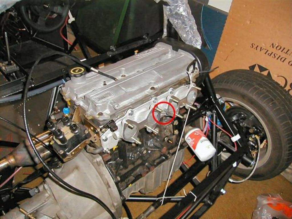
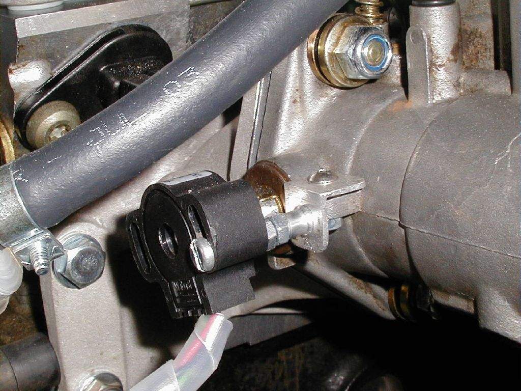
13th March: 3h30m: Remembered that I hadn't fitted the required spacer to the left rear engine mount. This is required because the same bolt is used to secure the lower wishbone and the engine mount- to ensure that the centre sections of the suspension / engine mount bushes are clamped securely. A bit difficult to explain... Anyway, the spacer was made from a 10mm length of small diameter aluminium tube. Decided to check the fit of the exhaust, as I was a little concerned that it was going to be very difficult to fit. First task was to physically get it into the gap behind the driver-side bulkhead- not as easy as it sounds! Thankfully, it will just slide in from the driver's side, pushed tightly up against the cambelt cover. The exhaust was now sat about 200mm below it's final install position. It soon became obvious that there was no way the exhaust could be raised to the correct position whilst the studs were still in place. This meant removing the studs (which I had left in place after removing the original Ford exhaust manifold), which unfortunately would have been a much easier task before the engine had been fitted! At least, I thought, the Ford studs have a star drive fitting on the end to make my life easier... Well, that would have been the case, except the star drive section snapped off 5 of the 9 studs! I had to resort to winding 2 nuts down each stud, locking the nuts off against each other, and then using the rearmost nut to wind out the stud. This was a slow process due to the lack of space in which to work, but at least I eventually managed to remove all 9 studs. I will buy a full set of 9 replacements from Ford, as the star drive will be useful for winding the studs back in with the manifold in place. As a quick clearance test, I raised the exhaust, inserted a new gasket and wound in a couple of the old studs to hold everything in place temporarily. Thankfully, this worked well, and at worst I have a whole 3mm clearance between the exhaust and the rear bulkhead- the driver's seat back is going to be toasty! In fact, I had been thinking for some time that I would invest in some heat reflective mat, after remembering the demo car being 'rather warm'- after now seeing how tight the clearance is, I will definitely be doing so! Finally, I couldn't resist fitting the inlet manifold. Firstly, this required attacking with a hacksaw! I had realised a while ago that the centre flange of the manifold would clash with the throttle linkage, and had posted a message on the Westfield Sports Car Club forums. Other people had come across the issue, and suggested removing this centre section. The area in question is ringed in the photo below:
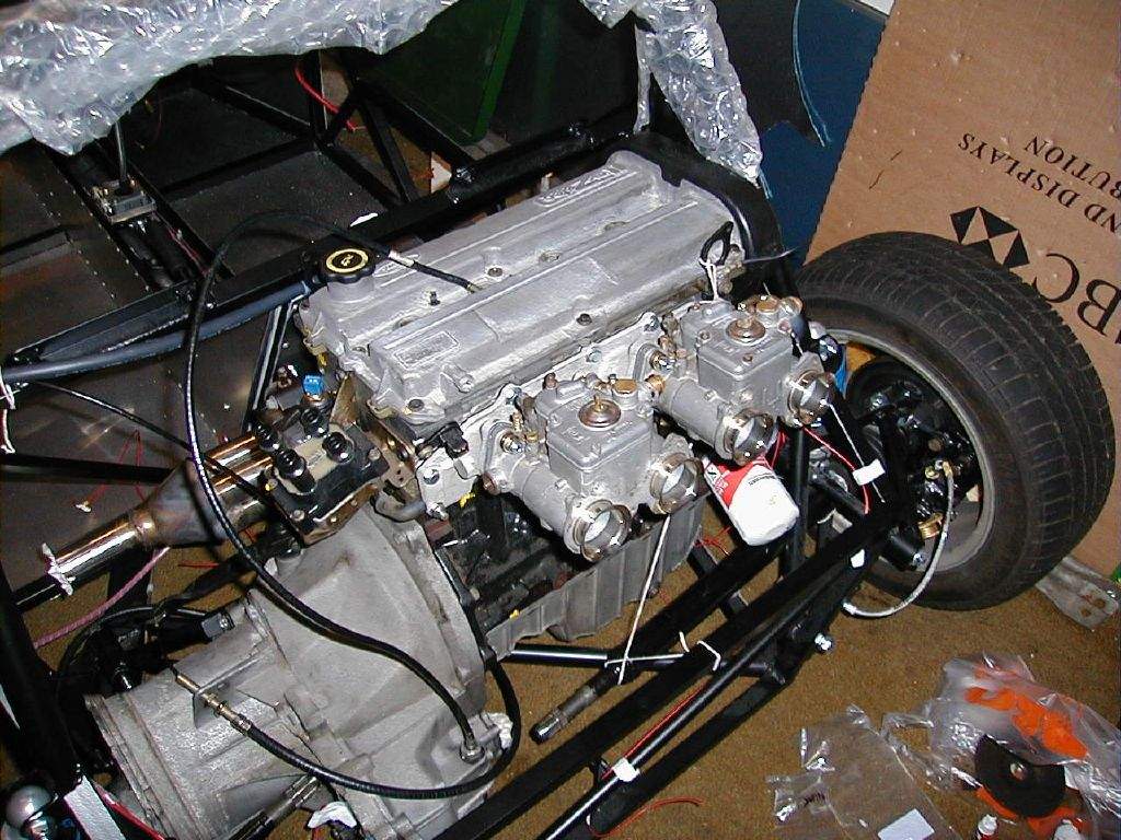
The hacksawing was of course done well away from the engine, and the manifold thoroughly cleaned out before fitting- aluminium filings are definitely not an engines best friend! 14th-19th March: I was in Germany on a training course all week, hence no progress on the Mojo... 20th March: 3h30m: Decided it was definitely time to get the carbs mounted. I had already bought the Misabs and other bits and pieces required from Burton Power, so it was just a matter of bolting things together:
21st March: 2h15m: Returned the engine hoist to its owner- thanks Stephen! Fitted the carb throttle linkage, firstly to the left hand carb, with the cable running down the tunnel. Soon realised that my cable stop at the pedal end of the cable was not going to be strong enough- the twin springs at the carb end meant quite a good shove is required on the pedal, and the aluminium bracket was visibly flexing under the strain. Hmmm... Noticed from the pictures of Jeremy's latest build (published in Kit Car magazine) that he has the throttle cable running down the outside of the chassis, with the linkage mounted on the right hand carb- I reckon this will give slightly fewer bends in the cable, hence less friction (a bit of a problem with such long cables). I swapped the linkage around, but the cable stop is still flexing far too much. A bit of reinforcement is called for... Fiddled with the handbrake setup- the cables are in place, but have never been connected to the lever. This sounds like an easy job, but as usual the confined space made life difficult! 22nd March: 2h00m: Started to beef up the throttle cable stop, which meant removing the 2 rivets on my original attempt, and adding a second piece of aluminium section. Once re-fitted, this was much better than before, so the 'feel' through the pedal was much improved, although I'm still a little concerned about the friction levels. Maybe these will improve once bedded in... Began working on getting the driveshafts fitted into the diff. The build manual suggests doing this as the engine is fitted, but seeing as I had the inner lobro joints removed from the driveshafts, there was enough clearance between the left and right shafts to drop the engine and gearbox in. I started on the left hand (short) driveshaft, jacking the rear corner, removing the wheel, unbolting the caliper and laying to one side, and then removing the upper ball joint from the upright. This enables the upright to be rotated outwards, enabling the inboard end of the driveshaft to move out also. I then fitted a new rubber boot to the shaft, snapped the lobro joint onto the end, and then shoved the whole lot into the diff housing. Easy! 23rd March: 1h00m: Fitted the right hand driveshaft.
24th & 25th March: The cold I picked up in Germany has developed... 2 days in bed and no work on Mojo! 26th-30th March: Still suffering with a rotten cold, so not really made any progress. This is frustrating!31st March: 1h30m: Back to work at last today, so I can justify some time in the garage… Made up a bracket for the speedo sender, which sits above the left hand lobro joint as it exits the diff. Stuck 4 equally spaced magnets to the outer surface of the lobro joint, using araldite type stuff (2 tubes of goo that you mix before applying). Attached the throttle pot to the left hand end of the throttle spindle, and devised a simple mounting bracket. Wired this back to the ECU connector in the tunnel.
Started having a look at the engine end of the radiator plumbing. I've got a header tank from a Sierra, plus a few bits of hose that I've picked up at various scrap yard trips, to avoid buying expensive silicone hose if possible. Total time spent during March: 32h15m
|
||||||||||||||||||||||||||||||||||||||||
|
|
||||||||||||||||||||||||||||||||||||||||||